
Basic Wind Loads -The Law and Implementation
After completing this course, you will:
Be better prepared and more authoritative in your work with wind loadings
Better understand common misgivings and misinformation about what to do and when to do it regarding wind loads Be aware of new avenues for you to reach out into

Introduction
Wind Loading
For a fun sample of what we are looking for in wind pressures, check out this web site and enter 300 as the size of a sail (a 10 foot high wall 30 feet long) and 110 as the wind speed:
Sail Wind Load Calculator Pretty impressive loads we need to restrain!
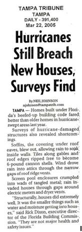
Below is a snippet out of a newspaper: As you can see, changes are eminent ? (note that she says ASCE 7-03 a publication that was not published! -or is she mistaken? Did she mean ASCE 7-02, the then future code? I believe so, she was speaking when ASCE 7-98 was still in force. Would you have known that?).
Florida Law changed after recent storms. The testing and coding underway by the American Society of Civil Engineers (ASCE), the American Society of Testing and Materials (ASTM) and standards developed by American National Standards Institute (ANSI) were quickly dusted off and made into law.
ASTM is a standards development organization that serves as an open forum for the development of
standards.
ANSI serves as administrator and coordinator of the United States private sector voluntary standardization
system.
Preface
History
The State of Florida first mandated statewide building codes during the 1970s at the beginning of the modern construction boom.
The first law required all municipalities and counties to adopt and enforce one of the four state-recognized model codes known as the “state minimum building codes.” During the early 1990s a series of natural disasters, together with the increasing complexity of building construction regulation in vastly changed markets, led to a comprehensive review of the state building code system. The study revealed that building code adoption and enforcement was inconsistent throughout the state and those local codes thought to be the strongest proved inadequate when tested by major hurricane events. The consequences of the building code failure were: devastation to lives and economies and a statewide property insurance crisis. The response was a reform of the state building construction regulatory system that placed emphasis on uniformity and accountability.
The 1998 Florida Legislature amended Chapter 553, Florida Statutes, Building Construction Standards, to create a single state building code that is enforced by local governments. As of March 1, 2002, the Florida Building Code superseded all local building codes which were developed and maintained by the Florida Building Commission. It is updated every three years and may be amended annually to incorporate interpretations and clarifications. The 2010 version will most likely include the new ASCE 7-10.
ASCE, ANSI, and ASTM
History
Prior to Hurricane Andrew (August 24, 1992), attention to wind load requirements was limited to selective geographic areas, primarily coastal zones with a high probability of hurricanes. In Florida, the South Florida Building Code (Dade and Broward Counties) has long recognized the need for buildings to be able to resist significant wind forces and has required product approval by the building department for use in that jurisdiction since the late 1970s. In years prior to Andrew, most other local code jurisdictions concerned about wind loading on garage doors accepted the Dade County-approved products for use in their own areas. The Dade County requirements at that time were for the products to be able to resist a specified design pressure that varied with the height of the door. These loads had to be confirmed by test in accordance with the procedures of ASTM E330, witnessed by registered engineers, and documented to Dade County.
After Hurricane Andrew, the general consensus of the engineering professionals and code officials was that there were deficiencies in the code regarding design for wind. It was noted that the South Florida Building Code had wind load requirements less than those recommended in the American Society of Civil Engineers (ASCE 7) document “Minimum Design Loads for Buildings and Other Structures.” The South Florida Building Code of 1994 was revised and the requirements of ASCE 7 were included in the new code. ASCE 7 requirements for components and cladding were based on the building location, plan dimensions, building height, distance from the ocean line, roof slope, location from the comer of the building, usage of the building, whether the building has significant openings in the envelope, and the opening size. The large number of parameters makes the determination of wind pressure “building specific.” For the first time, several different wind load pressures would be required for parts on the same building.
Standard ASCE/SEI 7 is now an integral part of most building codes in the United States. Many of the load provisions are substantially adopted by reference in the International Building Code and the NFPA 5000 Building Construction and Safety Code.
In 2010 the ASCE 7 revised the document, per ASCE: This newly revised standard offers a complete update and reorganization of the wind load provisions, expanding them from one chapter into six. ASCE 7-10 Minimum Design Loads for Buildings and Other Structures is being significantly revised this year. These revisions will affect every engineer who has used ASCE 7 in the past and those who are just beginning to use it for determining wind loads on structures. Some of the differences include, the determination of the basic wind speed with new wind speed maps, the classification of buildings, and simplified procedures have new methods for determining wind pressures for buildings as tall as 160 ft. Note that the pressures you calculate with ASCE 7-10 are ultimate values to be used with a 1.0 load factor vs. ASCE 7-05 pressures which were to be used with a 1.6 load factor so the pressures themselves should be different.
ASCE 7-10 contains a number of important updates to the General Requirements chapter. That chapter has been rewritten around the concept of risk-based design. The former Occupancy Categories have been renamed Risk Categories and, in addition, the laundry list of building types that fall under the various occupancies have been moved to the Commentary, so as to avoid conflict with the table contained in the building code. In addition, an extensive section on performance-based design procedures has been added, providing guidance for use of alternative means to the prescriptive requirements for justifying the adequacy of structural designs. These performance-based procedures, originally developed for seismic design, can be used for any load condition. Finally, the basic structural integrity provisions, which formerly appeared as requirements for Seismic Design Category A structures, have been moved to the General Chapter and clarified as being “structural integrity” rather than seismic requirements.
Windborne Debris
The changing wind speed numbers will have some effect on locations near the beach — because they effect the “triggers” for windborne debris requirements. Under ASCE 7-10, the parts of the coastline where buildings need impact-resistant glazing or storm shutters will be smaller. Besides a few barrier islands right along the shore, almost no place north of the southern tip of Florida will have to have impact glazing.
It became the responsibility of the building designer to determine the appropriate wind pressure for all parts of the building. Normally the building was assumed to be an “enclosed building,” as defined in the Standard Building in order to minimize internal pressures and additionally to protect the building contents. This requires that all components and cladding of the building be designed to resist the associated wind pressures accordingly.
As the garage door is typically the largest opening in a structure, and the area behind the door the largest open area within the building, it is essential the garage door be protected during high pressures associated with wind loads if the integrity of the envelope is to stay intact. It was readily witnessed immediately after Hurricane Andrew that if the garage door failed due to pressure loads, typically this caused the structure behind the doors to fail as well. This was most apparent in the residential sector of construction. Thus, the higher design pressures were factored into the revised Standard Building Codes of 1994. Although the SBC clearly established these new design pressures and the related requirements for testing and approval, the educational process for building officials throughout Florida and surrounding states was confusing at best. How one county or local jurisdiction interprets the new Code may differ dramatically from that of a neighboring jurisdiction. In addition, the SBC provided wind load maps in the Code, however, testing and approval submittals were performed in pressures, not wind speed. Architects and Engineers alike were uncertain what to design and typically left it up to the owner or component manufacturer to determine what was actually required on a job-by-job basis. Occasionally information and drawings submitted at time of permitting may have been different than the Building Official required at time of final inspection. To say the least, it was very confusing for a number of years.
California 2008:
INITIAL STATEMENT OF REASONS FOR PROPOSED BUILDING STANDARDS OF THE CALIFORNIA BUILDING STANDARDS COMMISSION REGARDING THE 2007 CALIFORNIA BUILDING CODE CALIFORNIA CODE OF REGULATIONS, TITLE 24, PART 2, VOLUME 2
The Administrative Procedure Act (APA) requires that an Initial Statement of Reasons be available to the public upon request when a rulemaking action is being undertaken. The following information required by the APA pertains to this particular rulemaking action:
STATEMENT OF SPECIFIC PURPOSE AND RATIONALE:
The purpose of this proposed action is to update the 2007 California Building Code (2007 CBC) based on new information since the adoption of 2007 CBC.
CHAPTER 16-STRUCTURAL DESIGN
Section 1609.1.1 and 1609.6 –The all heights wind provisions of ASCE 7 are time consuming and confusing.
Many engineers make significant errors in their use of this method. There is a simplified method in ASCE 7, but it is limited in use. SEAOC (Structural Engineers Association of California) have filed a petition with the California Building Standards Commission (CBSC) in accordance with California Code of Regulations (CCR) Title 24, Part 1: California Administrative Code, 2007 (CAC 2007) Article 1-8 to adopt an alternate method which is in full compliance with ASCE 7. This method is being considered by the ASCE 7 Wind Committee for adoption in ASCE 7-10 and have been approved by the International Code Council –Structural (ICC-S) Committee for incorporation into IBC 2009 pending final action. Adoption of this proposal in the California Building Code, 2007 (CBC 2007) will permit use of this simplified method in California starting in 2009 instead of 2011.
The derivation of this method from ASCE 7 Chapter 6 is as follows: Cnet values qz = 0.00256 Kz Kzt Kd V2 I Eqn 6-15 p = q G Cp − qi (GCpi) Eqn 6-17
p = 0.00256 Kh Kzt Kd V2 I G Cp − 0.00256 Kz Kzt Kd V2 I (GCpi)
Rearranging terms: p = ( 0.00256 V 2 Kh Kd G Cp − 0.00256 V 2 Kz Kd (GCpi)) Kzt I
Define: qz = 0.00256 V 2so: p = (qs Kh Kd G Cp − qs Kz Kd (GCpi)) Kzt I and: p = qs Kd ( Kh G Cp − Kz (GCpi)) Kzt I
For leeward wall and roof elements Kh = Kzso: p = qs Kz ( Kd (G Cp − (GCpi))) Kzt I Substitute Cnet = Kd (G Cp − (GCpi)) and we get: p = qs Kz Cnet Kzt I
which is Eqn. 16-36. For windward roof elements Kh ≈ Kz and the same relationship holds.
For buildings: Kd = 0.85 For rigid structures: G = 0.85 so: Cnet = 0.85 (0.85 Cp − (GCpi))
So in California, they had already implemented ASCE 7-10, even before it was published!
The International Building Code
Most of us are using the 2009 IBC. The code change process, however, is already underway for the next version of the I-Codes, to be published in early 2012. Members of the NCSEA Code Advisory Subcommittees recently attended related ICC Code Development Hearings. The major change in the 2012 IBC will be its adoption of the updated version of the Minimum Loads standard, ASCE 7-10: One of the most significant changes to this standard was the substantive technical and editorial revisions to the wind design requirements. Chapter 6 was reorganized and expanded into six chapters. Rather than using a single map to determine wind design speeds, a set of four maps will be used. These new maps, which are adjusted for occupancy importance, will yield wind forces at the Strength Design level. As a result, the load factor for wind in the Strength Design Load Combinations will be 1.0 and, in the Allowable Stress Design Level, the load factor will be 0.6.
ASCE 7-10 also adds a new simplified wind design with a 160-foot height limit. The Alternate All-Heights provisions which CSEA introduced into the 2009 IBC will remain in the 2012 IBC, giving engineers a chance to contrast and compare the two methods.
The new Florida Building Code has attempted to provide all parties with the tools to clarify many of the “gray” areas experienced in recent years. There are several major changes in the Code that should be studied carefully. Florida is trying to fit in the ASCE 7-10 into the next code cycle, so it would be effective sooner than usual.
1. The wind speeds are now stated in “3 second gust” speeds, as compared to the “sustained wind” measurements in the SBC. By definition, a sustained wind consists of “gusts” in excess of 120 percent of the original wind speed. If the SBC required 100 mph “wind speed” factor for a particular county, the new Code may require 120 mph windload “gusts” and
meet relatively the same pressure criteria. Attached is a sample matrix for wind load pressures as they relate to the new Code. You will see the pressures required are both positive and negative, and depend on door size, opening location, and building exposure as defined in the Code. It is important to note this is only a sample matrix, and your respective engineer or architect will be required to place the appropriate pressures on your respective drawings prior to submittal for permitting. (Please see Table 1606.1.6.1 of the new Code for geographic specific wind speed requirements.)
2. Section 1606.1.7 of the new Code requires five items related to wind loads which must be shown on construction
drawings at time of permitting:
a. Basic wind speed, mph.
b. Wind importance factor and building category.
c. Wind exposure -if more than one wind exposure is utilized, the wind exposure and applicable wind direction shall be indicated.
d. The applicable internal pressure coefficient.
e. Components and Cladding. The design wind pressures in terms of psf to be used for the design of exterior component cladding materials not specifically designed by the registered design professional.
There are several parameters to be considered when calculating door opening pressures, including building height, roof slope, end zone area, center zone area, exposure classification, and building classification. Several of these offer “factors” for reducing the standard pressure requirements. The matrix below has been calculated utilizing these reduction factors. It is important to note most of the counties in Florida, except Dade and Broward, have accepted Exposure “B” as a standard. However, it is important this be confirmed on a job-by-job basis with the governing officials.
As design pressures increase, so does the cost of design and manufacturing for most of the components used in buildings today. Review these individual requirements early; it can save you time and money once the project is started.
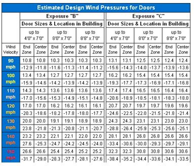
All loads listed above are an approximation and can vary from job to job.
Values based on a roof design with less than 10 degree pitch.
Roof height less than 15′ 0″.
Deduction taken for minor storage building.
Conclusions
In the beginning there were only ANSI codes for wind loads. South Florida also had its codes, and various building codes existed throughout the State (and also the U.S.) to accommodate what was thought of as a rare occurrence (so why bother?).
ASCE then took the ANSI codes and updated them. The International Code Council then grabbed the code from ASCE and made it theirs. The State of Florida looked around and then codified both the ASCE and the International Code, and made it into theirs.
Now we have a ruling body to put teeth into what was the recommended method. Now everyone has to take notice.
There are no reference materials for this course.
Current Florida Law
We are doing better, but we are not there yet, here is a newspaper clipping:
The first area of the code that is of interest is the requirement that the following be identified on the building plans:
1603.1.4 -Wind design data. The following information related to wind loads shall be shown, regardless of whether wind loads govern the design of the lateral-force-resisting system of the building:
1. Basic wind speed (3-second gust).
2. Wind importance factor, IW, and building classification from Table 1604.5 or Table 6-1, ASCE 7 and building classification in Table 1-1, ASCE 7.
3. Wind exposure, if more than one wind exposure is utilized, the wind exposure and applicable wind direction shall be indicated.
4. The applicable enclosure classifications and, if designing with ASCE 7, internal pressure coefficient.
5. Components and cladding. The design wind pressures in terms of psf (kN/m ) to be used for the design of exterior component and cladding materials not specifically designed by the registered design professional.
2
The paragraph above has generated a considerable amount of work in the state. The law is the backbone of a legislative effort to provide better-built homes, to reduce damage as much as possible.
Most likely due to the many hurricanes experienced lately year (especially the ones that criss-crossed the state), the state has implemented the following change to the law:
Hurricane Mitigation Retrofits
Pursuant to Section 553.833 of Florida Statutes, strengthening of existing site-built, single-family homes is now required under certain conditions. Below is a listing of specific circumstances in which mitigation is required:
1. When a roof on an existing site-built, single family residential structure is replaced. Roof-decking attachment and fasteners must be strengthened and corrected as required by the 2007 Manual of Hurricane Mitigation Retrofits for Existing Site-Built Single Family Residential Structures (The Guide,) Section 201.1. A secondary water barrier should be provided as required by section 201.2 of The Guide.
2. When a roof is replaced on a building that is located in the wind-borne debris region as defined in section 1609.2 of the Florida Building Code, Building and that has an insured value of $300,000 or more or, if the building is uninsured or for which documentation of insured value is not presented, has a just valuation for the structure for purposes of ad valorem taxation of $300,000 or more: a) Roof to wall connections shall be improved as required by section 201.3 of The Guide, b) Mandated retrofits of the roof-to-wall connection shall not be required beyond a 15 percent increase in the cost of re-roofing, c) Where complete retrofits of all the roof-to-wall connections as prescribed in Section 201.3 of The Guide would exceed 15 percent of the cost of the re-roofing project, the priorities outlined in Section 201.3.5 shall be used to limit the scope of work to the 15 percent limit.
3. When any activity requiring a building permit that is applied for on or after July 1, 2008, and for which the estimated cost is $50,000 or more for a building that is located in the wind borne debris region as defined in s. 1609.2 of the Florida Building Code, Building and that has an insured value of $750,000 or more, or, if the building is uninsured or for which documentation of insured value is not presented, has a just valuation for the structure for purposes of ad valorem taxation of $750,000 or more: a) Opening protections as required within the Florida Building Code, Building or Florida Building Code, Residential for new construction shall be provided.
4. When retrofit enhancement of gable end bracing is provided during construction which otherwise requires a permit, the techniques in Appendix A of The Guide shall be allowed.
Hurricane mitigation retrofits will take effect October 1, 2007.
Florida Building Code
The Florida Building Commission recently adopted the 2007 Florida Building Code. The effective date of the Code is October 1, 2008.
Below is the affected area for the above:
Florida Legislation: It’s More Than Hurricanes NAMIC Analysis Reveals
INDIANAPOLIS (May 13, 2005) -Although much of the attention during this year’s legislative session focused on hurricane-related issues, Florida lawmakers also succeeded in passing several other bills of interest to the insurance industry, a review by the National Association of Mutual Insurance Companies (NAMIC) has revealed.
“Lawmakers, for example, enacted two bills -House Bill 835 and Senate Bill 442 -which will result in significant changes being made to the state building code,”said NAMIC State Affairs Manager David Reddick.
House Bill 835 directs the Florida Building Commission to update the state Building Code with the most current edition of the wind protection requirements of the American Society of Civil Engineers, while Senate Bill 442 addresses a number of issues relating to the development and administration of the Florida Building Code and related building safety requirements.
Included in Senate Bill 442 are provisions that:
Provide that it is grounds for discipline for a building code administrator, engineer, or registered architect to perform building code inspections without necessary insurance;
Clarify provisions relating to truss placement plans and the code;
Require inspection of fire protection systems using national
standards; and
Make available from the Insurance Regulatory Trust Fund, an appropriation of $200,000 for the Florida Insurance Council and Florida Home Builders to develop a joint program to educate builders on the benefits and options of designing buildings for windborne debris protection.
Code Interpretation
Additional changes made to the code are found as follows:
SENATE STAFF ANALYSIS AND ECONOMIC IMPACT STATEMENT
Prepared By: Community Affairs Committee BILL: CS/SB 1232
SPONSOR: Community Affairs Committee and Senator Lynn SUBJECT: Wind-Protection Provisions of the Florida Building Code DATE: March 21, 2005
ANALYST STAFF DIRECTOR REFERENCE ACTION
I. Summary:
This committee substitute (CS) directs the Florida Building Commission to update the Florida Building Code with the most recent and relevant design standards for wind resistance of buildings issued by the American Society of Civil Engineers (ASCE Standard 7). The CS also repeals the current option for designing buildings to resist internal pressures when the Commission adopts the relevant national standards prohibiting such design options.
The CS appropriates $200,000 to the Department of Financial Services to develop a joint program between the Florida Insurance Council and the Florida Home Builders to educate builders on the benefits and options of designing buildings for windborne debris protection. The CS also requires the Commission and local building officials to evaluate the damage from Hurricane Ivan and make recommendations to the Legislature for changes to the Building Code as it relates to the region from the eastern border of Franklin County to the Florida-Alabama line.
Finally, the CS instructs the Commission to evaluate the definition of exposure category C in the Florida Building Code and make recommendations for changing the definition to the Legislature.
This CS amends section 109, Chapter 2000-141 of the Laws of Florida. This CS also creates unnumbered sections of the Florida Statutes.
The Florida Building Commission established standards for hurricane protection in the Florida Building Code that are based on a national model building code, federal regulations, and standards evolving out of southeast Florida’s experience with Hurricane Andrew. Specifically, for protection against hurricane waters, the Code incorporates the flood plain management standards of the Federal Emergency Management Agency’s National Flood Insurance Program for the entire state. For coastal construction it incorporates the Florida “coastal building zone” storm surge protection standards for coastal construction.
Design Standards for Wind Resistance -For protection against hurricane winds, the Florida Building Code adopts the national model building code engineering standard (American Society of Civil Engineers Standard 7 – ASCE 7). Buildings constructed in regions that are expected to experience hurricane winds of less than 120 mph must be designed to withstand external wind pressures identified for their location. Buildings constructed in regions that are expected to experience hurricane winds of 120 mph or greater must not only be able to withstand external wind pressures but also internal pressures that may result inside a building when a window or door is broken or a hole is created in its walls or roof by large debris. Areas within one mile of the coast that experience at least 110 mph winds are also required to meet the 120 mph standards for external and internal pressures.
The Florida Building Code requires that new homes throughout the state be designed to resist external wind speeds that the standard predicts these homes will experience sometime within a 50 to 100-year time period. In November of 1999, the Commission agreed with the developers of ASCE 7 and applied additional requirements in what is called the “wind-borne debris region” to ensure that buildings inside this region will also be able to withstand internal wind pressure caused by the penetration of flying debris. This region includes areas expected to experience winds of 120 mph or greater as well as areas within one mile of the coast that experience at least 110 mph winds.
Wind-Borne Debris Protection -Subsection (3) of s. 109 of ch. 2000-141, L.O.F., directs the Commission to adopt for areas of the state not within the high velocity hurricane zone, pursuant to s. 553.73, F.S., the wind protection requirements of the ASCE Standard 7.
However, the Legislature stipulated that from the eastern border of Franklin County to the Florida-Alabama line, only land within 1 mile of the coast is subject to the windborne-debris requirements adopted by the Commission. This subsection provides for the exact location of wind speed lines to be established by ordinance using specified physical landmarks, and provides that buildings constructed within the windborne debris region must be either designed for internal pressures resulting from a broken window or door or a hole in the walls or roof, or be designed with protected openings. The subsection further provides that except in the high velocity hurricane zone, local governments may not prohibit the option of designing buildings to resist internal pressures.
Exposure Category C. The ASCE 7 standard considers both wind speeds that can be developed by hurricanes and factors such as terrain and shielding by other buildings which effect the strength of those winds when they impact buildings.
Exposure A is characteristic of large cities with large expanses of tall buildings.
Exposure B is characteristic of suburban areas with large expanses of short and medium height buildings and wooded areas.
Exposure C is characteristic of areas of exposed expanses of open terrain or open water. Section 553.71, F.S., defines “exposure category C” to mean, except in the high velocity hurricane zone, that area which lies within 1,500 feet of the coastal construction control line, or within 1,500 feet of the mean high tide line, whichever is less. On barrier islands, exposure category C is applicable in the coastal building zone set forth in s. 161.55(5), F.S.
Commission Recommendations -In January, the Commission issued a report entitled, The Florida Building Code Commission Report to the 2005 Legislature. This report contained a number of recommendations to improve the effectiveness of the code. The report included the following specific recommendations relating to wind protection provisions:
Eliminate the edition designation and referenced amendments of the American Society of Civil Engineers, Standard 7 (ASCE 7) currently in Section 109, 2000-141, Laws of Florida, and allow updated editions of the standard to be adopted through updates to the Florida Building Code.
Eliminate the designation of the wind-borne debris region for the panhandle of Florida from Chapter 2000-141, Laws of Florida, and allow the wind-borne debris region for that area to be determined by the Florida Building Code.
Eliminate the definition of the wind exposure class C from s. 553.73, F.S., and allow the definition of ASCE 7 as
adopted by the Florida Building Code to be used.
Authorize the Commission to make determinations related to designing for internal pressures.
III. Effect of Proposed Changes:
Section 1 amends s. 109, ch. 2000-141, L.O.F., to require the Florida Building Commission to adopt the most current edition of the wind protection requirements of the American Society of Civil Engineers (ASCE) 7 Standard for the Minimum Design Loads for Buildings and Other Structures as the basis for structural design for wind in the Florida Building Code and removes the obsolete standard (1998 edition) from the Laws of Florida.
Section 2 creates a new section of law to remove the option for designing for internal pressure for buildings within the windborne debris region consistent with the International Building Code and International Residential Code. This section also requires the Commission to initiate rulemaking to incorporate the prohibition into the Florida Building Code when the base code is updated.
Section 3 appropriates $200,000 from the Insurance Regulatory Trust Fund to the Department of Financial Services to be used to develop a joint program between the insurance industry and the homebuilding industry to educate contractors on the benefits and options available for designing buildings for windborne protection to reduce property loss during a windstorm and to develop a standardized affidavit for verifying insurance discounts for storm-resistant residential construction techniques.
Section 4 provides that the Florida Building Commission, in conjunction with local building officials, shall conduct a review of damage resulting from the Hurricane Ivan and make recommendations to the Legislature for changes to the Florida Building Code as it relates to region from the eastern border of Franklin County to the Florida-Alabama line. The Commission must issue a report summarizing its findings and recommendations prior to the 2006 Regular Session.
Section 5 creates a new section to require the Florida Building Commission to evaluate the definition of exposure category C as currently defined in s. 553.71(10), F.S., and make recommendations for a new definition that more accurately depicts the Florida-specific conditions prior to the 2006 Legislative Session.
Section 6 provides for an effective date of July 1, 2005.
Text of HB 835(SB 1232) as it went to the Governor is as follows: HB 835
A bill to be entitled
- 1.
- 2. An act relating to wind-protection provisions of the
- 3. Florida Building Code; amending ch. 2000-141, Laws of
- 4. Florida; providing for removal of outdated wind-protection
- 5. standards from the Florida Building Code; providing for an
- 6. update of the code’s wind-protection standards; providing
- 7. an appropriation; providing for incorporation in the
- 8. Florida Building Code of the repeal of a design option
- 9. relating to internal pressure for buildings within the
- 10. windborne debris region; requiring the Florida Building
- 11. Commission to make recommendations to the Legislature;
- 12. providing an effective date.
- 13.
- 14. Be It Enacted by the Legislature of the State of Florida:
- 15.
- 16. Section 1. Subsection (3) of section 109 of chapter 2000
- 17. 141, Laws of Florida, is amended to read:
- 18. Section 109. The Legislature has reviewed the Florida
- 19. Building Code that was adopted by action of the Florida Building
- 20. Commission on February 15, 2000, and that was noticed for rule
- 21. adoption by reference in Rule 9B-3.047, F.A.C., on February 18,
- 22. 2000, in the Florida Administrative Weekly on page 731. The
- 23. Florida Building Commission is directed to continue the process
- 24. to adopt the code, pursuant to section 120.54(3), Florida
- 25. Statutes, and to incorporate the following provisions or
- 26. standards for the State of Florida:
- 27. (3) For areas of the state not within the high velocity
- 28. hurricane zone, the commission shall adopt, pursuant to s.
- 29. 553.73, Florida Statutes, the most current edition of the wind
- 30. protection requirements of the American Society of Civil
- 31. Engineers, Standard 7, 1998 edition as implemented by the
- 32. International Building Code, 2000 edition, and as modified by
- 33.
the commission in its February 15, 2000, adoption of the Florida - 34.
Building Code for rule adoption by reference in Rule 9B-3.047, - 35. Florida Administrative Code. However, from the eastern border of
- 36. Franklin County to the Florida-Alabama line, only land within 1
- 37. mile of the coast shall be subject to the windborne-debris
- 38. requirements adopted by the commission. The exact location of
- 39. wind speed lines shall be established by local ordinance, using
- 40. recognized physical landmarks such as major roads, canals,
- 41. rivers, and lake shores, wherever possible. Buildings
- 42. constructed in the windborne debris region must be either
- 43. designed for internal pressures that may result inside a
- 44. building when a window or door is broken or a hole is created in
- 45. its walls or roof by large debris, or be designed with protected
- 46. openings. Except in the high velocity hurricane zone, local
- 47. governments may not prohibit the option of designing buildings
- 48. to resist internal pressures.
- 49. Section 2. Notwithstanding any other provision of this
- 50. act, the option for designing for internal pressure for
- 51. buildings within the windborne debris region shall be repealed
- 52. immediately upon adoption of standards and conditions within the
- 53. International Building Code or International Residential Code
- 54. prohibiting such design option. The Florida Building Commission
- 55. shall initiate rulemaking to incorporate such standards and
- 56. conditions prohibiting designing for internal pressure for
- 57. buildings into the Florida Building Code when the base code is
- 58. updated.
- 59. Section 3. The Legislature appropriates, for fiscal year
- 60. 2005-2006 only, $200,000 from the Insurance Regulatory Trust
- 61. Fund to the Department of Financial Services to be used to
- 62. develop a joint program between the Florida Insurance Council
- 63. and the Florida Home Builders Association to educate contractors
- 64. on the benefits and options available for designing buildings
- 65. for windborne debris protection and to develop a standardized
- 66. affidavit to be used for verifying the insurance discounts for
- 67. residential construction techniques demonstrated to reduce the
- 68. amount of loss during a windstorm.
- 69. Section 4. The Florida Building Commission, in conjunction
- 70. with local building officials, shall conduct a review of damage
- 71. resulting from Hurricane Ivan and any other data to evaluate,
- 72. and to make recommendations to the Legislature for any changes
- 73. to, Florida’s Building Code, specifically as it applies to the
- 74. region from the eastern border of Franklin County to the
- 75. Florida-Alabama line. The commission shall issue a report
- 76. summarizing its findings and recommendations prior to the 2006
- 77. Regular Session.
- 78. Section 5. The Florida Building Commission shall evaluate
- 79. the definition of “exposure category C” as currently defined in
- 80. section 553.71(10), Florida Statutes, and make recommendations
- 81. for a new definition that more accurately depicts Florida
- 82. specific conditions prior to the 2006 Regular Session.
Section 6. This act shall take effect July 1, 2005. - 83.
CODING: Words stricken are deletions; words underlined are additions.
This new criteria was approved, it is a sign of the state of the art of the laws of Florida.
Conclusions
The following is a portion of the International Code:
SECTION 1609 (International Code) WIND LOADS
1609.1 APPLICATIONS: Buildings, structures and parts thereof shall be designed to withstand the minimum wind loads prescribed herein. Decreases in wind loads shall not be made for the effect of shielding by other structures.
1609.1.1 -Determination of wind loads. Wind loads on every building or structure shall be determined in accordance with Section 6 of ASCE 7. Wind shall be assumed to come from any horizontal direction and wind pressures shall be assumed to act normal to the surface considered.
Exceptions :
1. Wind loads determined by the provisions of Section 1609.6.
2. Subject to the limitations of Section 1609.1.1.1, the provisions of SBCCI SSTD 10 Standard for Hurricane Resistant Residential Construction shall be permitted for applicable Group R2 and R3 buildings.
3. Subject to the limitations of Section 1609.1.1.1, residential structures using the provisions of the AF&PA Wood Frame Construction Manual for One-and Two-Family Dwellings.
4. Designs using NAAMM FP 1001 Guide Specification for Design of Metal Flagpoles.
5. Designs using TIA/EIA-222 for antenna-supporting structures and antennas.
Following is a portion of the Florida Building Code:
SECTION 1609 (Florida Building Code) WIND LOADS
1609.1 APPLICATIONS: Buildings, structures and parts thereof shall be designed to withstand the minimum wind loads prescribed herein. Decreases in wind loads shall not be made for the effect of shielding by other structures.
1609.1.1 -Determination of wind loads. Wind loads on every building or structure shall be determined in accordance with Section 6 of ASCE 7.Wind shall be assumed to come from any horizontal direction and wind pressures shall be assumed to act normal to the surface considered.
Exceptions :
1. Provisions of Section1609.6 shall be permitted for buildings 60 feet (18.3 m) high or less.
2. Wind tunnel tests together with applicable sections of 1609.6.
3. Subject to the limitations of Sections 1609.1.1.1, 1609.1.4, and 1609.3, the provisions of SBCCI SSTD 10 shall be permitted for applicable Group R2 and R3 buildings for a basic wind speed of 130 mph (58 m/s) or less in Exposure B and 110 mph (49 m/s) or less in Exposure C in accordance with Figure 1609 and Section 1609.4.
4. Subject to the limitations of Sections 1609.1.1.1, 1609.1.4, and 1609.3, provisions of ANSI/AF&PA WFCM, Wood Frame Construction Manual for One-and Two-Family Dwellings shall be permitted for applicable wood frame buildings of Group R3 occupancy for a basic wind speed of 150 mph or less in accordance with Figure 1609 and Section 1609.4.
5. Designs using NAAMM FP-1001 Specification for Design Loads of Metal Flagpoles.
6. Subject to the limitations of Sections 1609.1.1.1, 1609.1.4, and 1609.3, the provisions of the FC&PA Guide to Concrete Masonry Residential Construction in High Wind Areas shall be permitted for applicable concrete masonry buildings of Group R3 occupancy for a basic wind speed of 130 mph (58 m/s) or less in Exposure B and 110 mph (49 m/s) or less in Exposure C in accordance with Figure 1609 and Section 1609.4.
7. ANSI/TIA/EIA222 shall be permitted for communication tower and steel antenna support structures and shall meet the wind loads of ASCE 7 and shall be designed by a qualified engineer.
Do you see any similarities? The FLORIDA code was lifted right off the International Code, then modified to suit.
References
[NOTE: not all tables are included below for clarity and brevity] In addition to Section 1609 below, there are Roofing Application Standards (RAS) and Testing Application Standards (TAS) which may be of interest. They can also be found at the above link.
SECTION 1609: WIND LOADS
1609.1 -APPLICATIONS: Buildings, structures and parts thereof shall be designed to withstand the minimum wind loads prescribed herein. Decreases in wind loads shall not be made for the effect of shielding by other structures.
1609.1.1 -Determination of wind loads .Wind loads on every building or structure shall be determined in accordance with Section 6 of ASCE 7.Wind shall be assumed to come from any horizontal direction and wind pressures shall be assumed to act normal to the surface considered.
Exceptions :
1. Provisions of Section1609.6 shall be permitted for buildings 60 feet (18.3 m) high or less.
2. Wind tunnel tests together with applicable sections of 1609.6.
3. Subject to the limitations of Sections 1609.1.1.1, 1609.1.4, and 1609.3, the provisions of SBCCI SSTD 10 [Standard Building Code -Provides design and construction details for improving the structural performance of single and multi-family dwellings, this is referenced many times, as well as ANSI for construction details and ASTM 7 for wind loading.] shall be permitted for applicable Group R2 and R3 buildings for a basic wind speed of 130 mph (58 m/s) or less in Exposure B and 110 mph (49 m/s) or less in Exposure C in accordance with Figure 1609 and Section 1609.4.
4. Subject to the limitations of Sections 1609.1.1.1, 1609.1.4, and 1609.3, provisions of ANSI/AF&PA WFCM, Wood Frame Construction Manual for One-and Two-Family Dwellings shall be permitted for applicable wood frame buildings of Group R3 occupancy for a basic wind speed of 150 mph or less in accordance with Figure 1609 and Section 1609.4.
5. Designs using NAAMM FP-1001 Specification for Design Loads of Metal Flagpoles.
6. Subject to the limitations of Sections 1609.1.1.1, 1609.1.4, and 1609.3, the provisions of the FC&PA Guide to Concrete Masonry Residential Construction in High Wind Areas shall be permitted for applicable concrete masonry buildings of Group R3 occupancy for a basic wind speed of 130 mph (58 m/s) or less in Exposure B and 110 mph (49 m/s) or less in Exposure C in accordance with Figure 1609 and Section 1609.4.
7. ANSI/TIA/EIA222 shall be permitted for communication tower and steel antenna support structures and shall meet the wind loads of ASCE 7 and shall be designed by a qualified engineer.
8. Subject to the limitations of Sections 1609.1.1.1, 1609.1.4, and 1609.3, the provisions of the WPPC Guide to Wood Construction in High Wind Areas shall be permitted for applicable wood-frame buildings of Group R3 occupancy for a basic wind speed of 130 mph (58 m/s) or less in Exposure B and 110 mph (49 m/s) or less in Exposure C in accordance with Figure 1609 and Section 1609.4.
9. Designs using AASHTOLTS-4 Structural Specifications for Highway Signs, Luminaries, and Traffic
Signals.
1609.1.1.1 -Applicability . The provisions of SSTD 10, the AF&PA Wood Frame Construction Manual for One and Two-Family Dwellings, High Wind Edition, the FC . The provisions of SSTD 10, the AF&PA Wood Frame Construction Manual for One and Two-Family Dwellings, High Wind Edition, the FC & PA Guide to Concrete Masonry Residential Construction in High Wind Areas, and the WPPC Guide to Wood Construction in High Wind Areas are applicable only to buildings located within Exposure A, B or C as defined in Section 1609.4. The provisions shall not apply to buildings sited on the upper half of an isolated hill, ridge, or escarpment meeting the following conditions:
1. The hill, ridge or escarpment is 60 feet (18.3 m) or higher if located in exposure B or 30 feet
(9.1 m) or higher if located in exposure C;
2. The maximum average slope of the hill exceeds 10 percent; and
3. The hill, ridge or escarpment is unobstructed upwind by other such topographic features for a distance from the high point of 50 times the height of the hill or 1 mile (1.6 km), whichever is greater.
1609.1.2 -Minimum wind loads . The wind loads used in the design of the main wind-force-resisting system
shall not be less than 10 psf (0.479 kN/m2 ) multiplied by the area of the building or structure projected on a vertical plane normal to the wind direction. In the calculation of design wind loads for components and cladding for buildings, the algebraic sum of the pressures acting on opposite faces shall be taken into account. The
design pressure for components and cladding of buildings shall not be less than 10 psf (0.479 kN/m2) acting in either direction normal to the surface. The design force for open buildings and other structures shall not be less
than 10 psf (0.479 kN/m2) multiplied by the area Af.
1609.1.3 -Anchorage against overturning, uplift and sliding . Structural members and systems and components and cladding in a building or structure shall be anchored to resist wind-induced overturning, uplift and sliding and to provide continuous load paths for these forces to the foundation. Where a portion of the resistance to these forces is provided by dead load, the dead load, including the weight of soils and foundations, shall be taken as the minimum dead load likely to be in place during a design wind event. Where the alternate basic load combinations of Section 1605.3.2 are used, only two-thirds of the minimum dead load likely to be in place during a design wind event shall be used.
1609.1.4 -Protection of openings . In wind-borne debris regions, exterior glazing that receives positive pressure in the lower 60 feet (18.3 m) in buildings shall be assumed to be openings and the balance of glazed openings in the rest of the building shall be assumed to be zero unless such glazing that receives positive pressure is impact resistant or protected with an impact resistant covering meeting the requirements of SSTD 12, ASTM E 1886 and ASTM E 1996, or Miami-Dade TAS 201, 202 and 203 referenced therein as follows:
1. Glazed openings located within 30 feet (9.1 m) of grade shall meet the requirements of the Large Missile Test.
2. Glazed openings located more than 30 feet (9.1 m) above grade shall meet the provisions of the Small Missile Test.
3. Storage sheds that are not designed for human habitation and that have a floor area of 720 square feet
(67 m2) or less are not required to comply with the mandatory windborne debris impact standards of this code.
Openings in sunrooms, balconies or enclosed porches constructed under existing roofs or decks are not required to be protected provided the spaces are separated from the building interior by a wall and all openings in the separating wall are protected in accordance with Section 1609.1.4 above. Such spaces shall be permitted to be designed as either partially enclosed or enclosed structures.
Exceptions:
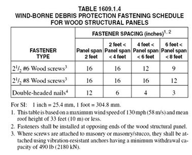
1. Wood structural panels with a minimum thickness of 7/16 inch (11.1 mm) and maximum panel span of 8 feet (2438 mm) shall be permitted for opening protection in one-and two-story buildings. Panels shall be precut to cover the glazed openings with attachment hardware provided. Attachments shall be designed to resist the components and cladding loads determined in accordance with the provisions of Section 1609.6.5. Attachment in accordance with Table 1609.1.4 is permitted for buildings with a mean height of 33 feet (10 058 mm) or less where wind speeds do not exceed 130 mph (57.2 m/s).
2. Buildings in Category I as defined in Table 1604.5, including production greenhouses as defined in
Section 1602.
1609.1.4.1 -Building with openings . Where glazing is assumed to be an opening in accordance with Section 1609.1.4, the building shall be evaluated to determine if the openings are of sufficient area to constitute an open or partially enclosed building as defined in Section 1609.2. Open and partially enclosed buildings shall be designed in accordance with the applicable provisions of ASCE 7.
1609.1.4.2 -Optional exterior door component testing . Exterior side-hinged door assemblies shall have the option to have the components of the assembly tested and rated for impact resistance in accordance with the following specification: SDI 250.13.
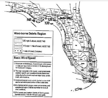
Figure 1609: State of Florida Wind Borne Debris Region & Basic Wind Speed
1609.1.5 The wind-borne debris regions requirements shall not apply landward of the designated contour line in Figure 1609. Ageographical boundary that coincides with the contour line shall be established.
1609.2 -DEFINITIONS:
The following words and terms shall, for the purposes of Section 1609.6, have the meanings shown herein.
Buildings and Other Structures,
Flexible: Slender buildings and other structures that have a fundamental natural frequency less than 1 Hz.
Building, Enclosed: A building that does not comply with the requirements for open or partially enclosed buildings.
Building, Low-Rise: Enclosed or partially enclosed buildings that comply with the following conditions:
- 1. Mean roof height, h, less than or equal to 60 feet (18 288 mm).
- 2. Mean roof height, h, does not exceed least horizontal dimension.
Building, Open: A building having each wall at least 80 percent open. This condition is expressed for each wall by the
equation:
Ao >= 0.8Ag (Equation 16-31)
where:
2
A = Total area of openings in a wall that receives positive external pressure, in square feet (m).
o
2
A = The gross area of that wall in which Ao is identified, in square feet (m).
g
Building, Partially Enclosed: A building that complies with both of the following conditions:
- 1. The total area of openings in a wall that receives positive external pressure exceeds the sum of the areas of openings in the balance of the building envelope (walls and roof) by more than 10 percent; and
- 2. The total area of openings in a wall that receives positive external pressure exceeds 4 square feet (0.37 m 2) or 1 percent of the area of that wall, whichever is smaller, and the percentage of openings in the balance of the building envelope does not exceed 20 percent.
These conditions are expressed by the following equations:
Ao > 1.10 Aoi (Equation 16-32)
2
Ao > 4 square feet (0.37m ) or > 0.01 A , whichever is smaller,
g
and Aoi /Agi 0.20 (Equation 16-33)
where:
A , Ag are as defined for an open building.
o
2
Aoi = The sum of the areas of openings in the building envelope (walls and roof) not including A, in square feet (m ).
o
= The sum of the gross surface areas of the building envelope (walls and roof) not including A , in square feet (m ).
Agi g2
Building, Simple Diaphragm: A building which complies with all of the following conditions:
1. enclosed building,
2. mean roof height, h, less than or equal to 60 feet (18 m),
3. mean roof height, h, does not exceed least horizontal dimension,
4. building has an approximately symmetrical cross section,
5. building has no expansion joints or structural separations within the building,
6. wind loads are transmitted through floor and roof diaphragms to the vertical lateral-force-resisting systems,
7. if the building has moment-resisting frames, roof slopes do not exceed 30 percent.
Components and Cladding: Elements of the building envelope that do not qualify as part of the main
windforce-resisting system.
Effective Wind Area: The area used to determine GC . For component and cladding elements, the effective wind area
p
in Tables 1609.6B and 1609.6C is the span length multiplied by an effective width that need not be less than one-third the span length. For cladding fasteners, the effective wind area shall not be greater than the area that is tributary to an individual fastener.
Hurricane-Prone Regions: Areas vulnerable to hurricanes defined as:
1. The U.S. Atlantic Ocean and Gulf of Mexico coasts where the basic wind speed is greater than 90 mph (39.6 m/s) and
2. Hawaii, Puerto Rico, Guam, Virgin Islands and American Samoa. Importance Factor, Iw: A factor that accounts for the degree of hazard to human life and damage to property. Main Windforce-Resisting System: An assemblage of structural elements assigned to provide support and stability for
the overall structure. The system generally receives wind loading from more than one surface.
Mean Roof height: The average of the roof eave height and the height to the highest point on the roof surface, except
that eave height shall be used for roof angle of less than or equal to 10 degrees (0.1745 rad).
Wind-Borne Debris Region:
- 1. Areas within one mile (1.6 km) of the coastal mean high water line where the basic wind speed is 110 mph (49 m/s) or greater.
- 2. Areas where the basic wind speed is 120 mph (53 m/s) or greater except from the eastern border of Franklin County to the Florida-Alabama line where the region includes areas only within 1 mile of the coast.
1609.3 -BASIC WIND SPEED: The basic wind speed in miles per hour, for the development of wind loads, shall be determined from Figure 1609. Basic wind speed for the special wind regions indicated, near mountainous terrain and near gorges shall be in accordance with local jurisdiction requirements. The exact location of wind speed lines shall be established by local ordinance using recognized physical landmarks such as major roads, canals, rivers and lake shores, wherever possible.
1609.3.1 -Wind speed conversion . When required, the 3-second gust wind velocities of Figure 1609 shall be converted to fastest-mile wind velocities usingTable 1609.3.1.
1609.4 -EXPOSURE CATEGORY. For each wind direction considered, an exposure category that adequately reflects the characteristics of ground surface irregularities shall be determined for the site at which the building or structure is to be constructed. For a site located in the transition zone between categories, the category resulting in the largest wind forces shall apply. Account shall be taken of variations in ground surface roughness that arise from natural topography and vegetation as well as from constructed features. For any given wind direction, the exposure in which a specific building or other structure is sited shall be assessed as being one of the following categories. When applying the simplified wind load method of Section 1609.6, a single exposure category shall be used based upon the most restrictive for any given wind direction.
- 1. Exposure A. Large city centers with at least 50 percent of the buildings having a height in excess of 70 feet (21.3 m). Use of this exposure category shall be limited to those areas for which terrain representative of Exposure A prevails in the upwind direction for a distance of at least one-half mile (0.8 km) or 10 times the height of the building or other structure, whichever is greater. Possible channeling effects or increased velocity pressures caused by the building or structure being located in the wake of adjacent buildings shall be taken into account.
- 2. Exposure B. Urban and suburban areas, wooded areas or other terrain with numerous closely spaced
obstructions having the size of single-family dwellings or larger. Exposure B shall be assumed unless the site
meets the definition of another type of exposure. - 3. Exposure C. Means, except in the high-velocity hurricane zone, that area which lies within 1,500 feet (46 m) of the coastal construction control line, or within 1,500 feet (46 m) of the mean high tide line, whichever is less. On barrier islands, exposure category C shall be applicable in the coastal building zone set forth in Section
- 4. Exposure D. Flat, unobstructed areas exposed to wind flowing over open water (excluding shorelines in hurricane-prone regions) for a distance of at least 1 mile (1.61 km). Shorelines in Exposure D include inland waterways, the Great Lakes and coastal areas of California, Oregon, Washington and Alaska. This exposure shall apply only to those buildings and other structures exposed to the wind coming from over the water. Exposure D extends inland from the shoreline a distance of 1,500 feet (460 m) or 10 times the height of the building or structure, whichever is greater.
1609.5 -IMPORTANCE FACTOR: Buildings and other structures shall be assigned a wind load importance factor, Iw, in accordance with Table 1604.5.
1609.6 -SIMPLIFIED PROVISIONS FOR LOW-RISE BUILDINGS
1609.6.1 Scope -Procedures in Section 1609.6 shall be used for determining and applying wind pressures in the design of simple diaphragm buildings with flat, hipped and gable-shaped roofs having a mean roof height not exceeding the least horizontal dimension of the building or 60 feet (18.3 m), whichever is less.
The provisions of Section 1609.6 shall not be used if any of the following conditions exist:
1. Buildings on which exterior glazing is considered to be openings in accordance with Section 1609.1.4.
2. Buildings sited on the upper half of an isolated hill or escarpment meeting all the following conditions:
a. The hill or escarpment is 60 feet (18.3 m) or higher if located in exposure B or 30 feet (9.1 m) or higher if located in Exposure C.
b. The maximum average slope of the hill exceeds 10 percent.
c. The hill or escarpment is unobstructed upwind by other such topographic features for a distance from the high point of 50 times the height of the hill or 1 mile (1.6 km), whichever is less.
1609.6.1.1 Reserved. 1609.6.1.2 Reserved.

1609.6.2 Wind pressures.
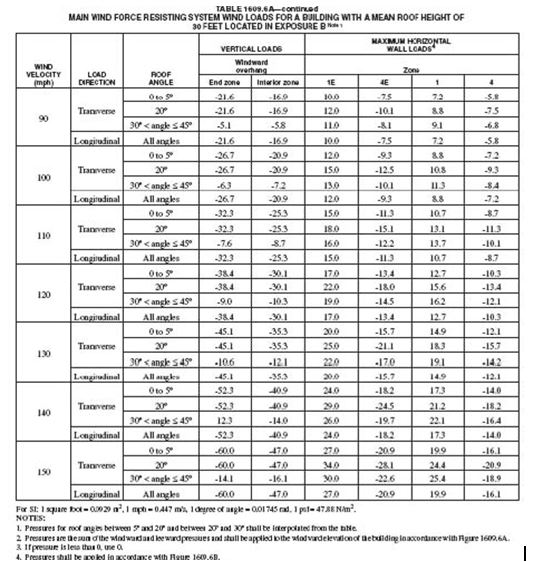
1609.6.2.1 –Structural members, cladding, fasteners and systems providing for the structural integrity of the building shall be designed for the loads from Table 1609.6A, Table 1609.6B and Table 1609.6C using Figure 1609, multiplied by the appropriate height and exposure coefficient from Table 1609.6D and the importance factor from Table 1604.5.
1609.6.2.2 –Members that act as both part of the main wind-force-resisting system and as components and cladding shall be designed for each separate load case.
1609.6.3 -Edge strips and end zones. The width of the edge strips (a), as shown in Figure 1609.6C, shall be 10 percent of the least horizontal dimension or 40 percent of the eave height, whichever is less but not less than either 4 percent of the least horizontal dimension or 3 feet (914 mm). End zones as shown in Figure 1609.6B shall be twice the width of the edge strip (a).
1609.6.4 -Main wind force resisting system (MWFRS). All elements and connections of the MWFRS shall be designed for vertical and horizontal loads based on the combined leeward and windward wall pressures and roof pressures determined from Table 1609.6A. Pressures shall be applied in accordance with the loading diagrams shown in Figure 1609.6A to the end zone and interior zone as shown in Figure 1609.6B. The building shall be designed for all wind directions. For buildings having flat roofs, a ridge line normal to the wind direction shall be assumed at the midlength dimension of the roof for all directions considered. Each corner shall be considered in turn as the windward corner.
1609.6.4.1 -Overhang loads. The pressures to be used for the effects of roof overhangs on MWFRS shall be taken from Table 1609.6A and include the effect of the wind on both the bottom and top surfaces.
1609.6.5 –Components and cladding. Pressure for wind loading actions on components and cladding shall be determined from Table 1609.6B for enclosed portions of the building and Table 1609.6C for overhangs, based on the effective area for the element under consideration. The pressures in Table 1609.6C include internal pressure. The pressure shall be applied in accordance with the loading diagrams in Figure 1609.6C.
1609.6.5.1 -Garage doors. Pressures from Table 1609.6E. for wind loading actions on garage doors for
buildings designed as enclosed shall be permitted.
1609.7 -ROOF SYSTEMS
1609.7.1 -Roof deck . The roof deck shall be designed to withstand the wind pressures determined under either the provisions of Section 1609.6 for buildings with a mean roof height not exceeding 60 feet (18 288 mm) or Section 1609.1.1 for buildings of any height.
1609.7.2 -Roof coverings . Roof coverings shall comply with Section 1609.7.1.
Exception :
Rigid tile roof coverings that are air permeable and installed over a roof deck complying with Section
1609.7.1 are permitted to be designed in accordance with Section 1609.7.3.
1609.7.3 -Rigid tile . Wind loads on rigid tile roof coverings shall be determined in accordance with the following equation (equation 16-36):
.
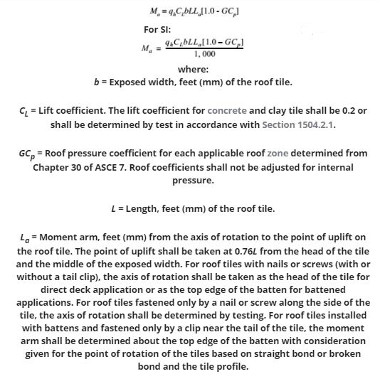
Concrete and clay roof tiles complying with the following limitations shall be designed to withstand the aerodynamic uplift moment as determined by this section.
1. The roof tiles shall be either loose laid on battens, mechanically fastened, mortar set or adhesive set.
2. The roof tiles shall be installed on solid sheathing which has been designed as components and cladding.
3. An underlayment shall be installed in accordance with Chapter 15.
4. The tile shall be single lapped interlocking with a minimum head lap of not less than 2 inches (51 mm).
5. The length of the tile shall be between 1.0 and 1.75 feet (305 mm and 533 mm).
6. The exposed width of the tile shall be between 0.67 and 1.25 feet (204 mm and 381 mm).
7. The maximum thickness of the tail of the tile shall not exceed 1.3 inches (33 mm).
8. Roof tiles using mortar set or adhesive set systems shall have at least two-thirds of the tile’s area free of mortar or adhesive contact.
SECTION 1610 SOIL LATERAL LOAD
1610.1 -GENERAL: Basement, foundation and retaining walls shall be designed to resist lateral soil loads. Soil loads specified inTable 1610.1 shall be used as the minimum design lateral soil loads unless specified otherwise in a soil investigation report approved by the building official. Basement walls and other walls in which horizontal movement is restricted at the top shall be designed for at-rest pressure. Retaining walls free to move and rotate at the top are permitted to be designed for active pressure. Design lateral pressure from surcharge loads shall be added to the lateral earth pressure load. Design lateral pressure shall be increased if soils with expansion potential are present at the site.
Exception:
Basement walls extending not more than 8 feet (2438 mm) below grade and supporting flexible floor systems shall be permitted to be designed for active pressure.
SECTION 1611: RAIN LOADS
1611.1 -DESIGN RAIN LOADS: Each portion of a roof shall be designed to sustain the load of rainwater that will accumulate on it if the primary drainage system for that portion is blocked plus the uniform load caused by water that rises above the inlet of the secondary drainage system at its design flow.
R= 5.2 (ds + dh) (Equation 16-37)
For SI: R = 0.0098 (ds + dh)
where:
dh = Additional depth of water on the undeflected roof above the inlet of secondary drainage system at its design flow (i.e., the hydraulic head), in inches (mm).
ds = Depth of water on the undeflected roof up to the inlet of secondary drainage system when the primary drainage system is blocked (i.e., the static head), in inches (mm).
R = Rain load on the undeflected roof, in psf (kN/m 2). When the phrase “undeflected roof” is used, deflections from loads (including dead loads) shall not be considered when determining the amount of rain on the roof.
1611.2 -PONDING INSTABILITY: Ponding refers to the retention of water due solely to the deflection of relatively flat roofs. Roofs with a slope less than one-fourth unit vertical in 12 units horizontal (2-percent slope) shall be investigated by structural analysis to ensure that they possess adequate stiffness to preclude progressive deflection (i.e., instability) as rain falls on them or meltwater is created from snow on them. The larger of snow load or rain load shall be used in this analysis. The primary drainage system within an area subjected to ponding shall be considered to be blocked in this analysis.
1611.3 -CONTROLLED DRAINAGE: Roofs equipped with hardware to control the rate of drainage shall be equipped with a secondary drainage system at a higher elevation that limits accumulation of water on the roof above that elevation. Such roofs shall be designed to sustain the load of rainwater that will accumulate on them to the elevation of the secondary drainage system plus the uniform load caused by water that rises above the inlet of the secondary drainage system at its design flow determined from Section 1611.1. Such roofs shall also be checked for ponding instability in accordance with Section 1611.2.
SECTION 1612: HIGHVELOCITY HURRICANE ZONES: GENERAL
1612.1 -GENERAL DESIGN REQUIREMENTS
1612.1.1 –Any system, method of design or method of construction shall admit of a rational analysis in
accordance with well-established principles of mechanics and sound engineering practices.
1612.1.2 -Buildings, structures and all parts thereof shall be designed and constructed to be of sufficient strength to support the estimated or actual imposed dead, live, wind, and any other loads, both during construction and after completion of the structure, without exceeding the allowable materials stresses specified by this code.
1612.1.3 -No building structure or part thereof shall be designed for live loads less than those specified in this Chapter or ASCE 7 with commentary, except as otherwise noted in this code.
1612.1.4 –The live loads set forth herein shall be assumed to include the ordinary impact but where loading involves unusual impact, provision shall be made by increasing the assumed live load.
1612.1.5 -In the design of floors, not less than the actual live load to be imposed shall be used. Special
provisions shall be made for machine or apparatus loads where applicable.
1612.1.6 –Floor and roof systems shall be designed and constructed to transfer horizontal forces to such parts of the structural frame as are designed to carry these forces to the foundation. Where roofs or floors are constructed of individual prefabricated units and the transfer of forces to the building frame and foundation is totally or partially dependent on such units, the units and their attachments shall be capable of resisting applied loads in both vertical and both horizontal directions. Where roofs or floors are constructed of individual prefabricated units and the transfer of forces to the building frame and foundation is wholly independent of such units, the units and their attachments shall be capable of resisting applied loads normal to the surface, in and out.
1612.2 -GENERAL DESIGN FOR SPECIFIC OCCUPANCIES AND STRUCTURES
1612.2.1 -Fences . Fences not exceeding 6 feet (1829 mm) in height from grade may be designed for 75 mph (33 m/s) fastest mile wind speed or 90 mph (40 m/s) 3-second gust. 1612.2.1.1 -Wood fences .Wood fence design shall be as specified by Section 2328. 1612.2.2 -Sway forces in stadiums.
1. The sway force applied to seats in stadiums, grandstands, bleachers and reviewing stands shall be not less than 24 pounds per lineal foot (350 N/m), applied perpendicularly and along the seats.
2. Sway forces shall be applied simultaneously with gravity loads.
3. Sway forces need not be applied simultaneously with other lateral forces.
SECTION 1613: HIGHVELOCITY HURRICANE ZONES: DEFLECTION
1613.1 -ALLOWABLE DEFLECTIONS: The deflection of any structural member or component when subjected to live, wind and other superimposed loads set forth herein shall not exceed the following:
1. Roof and ceiling or components supporting plaster = L/360
2. Roof members or components not supporting plaster under = L/240
3. Floor members or components = L/360
4. Vertical members and wall members or components consisting of or supporting material that hardens in place, is brittle or lacks resistance to cracking caused by bending strains = L/360
5. Vertical members and wall members or components not required to meet the conditions of Section 1613.1, item 4 = L/180
6. Roof and vertical members, wall members and panels of carports, canopies, marquees, patio covers, utility sheds and similar minor structures not to be considered living areas, where the roof projection is greater than 12 feet
(3.7 m) in the direction of the span, for free-standing roofs and roofs supported by existing structures.
Existing structures supporting such roofs shall be capable of supporting the additional loading = L/180
7. For Group R3 occupancies only, roof and vertical members, wall members and panels of carports, canopies, marquees, patio covers, utility sheds and similar minor structures not to be considered living areas, where the roof projection is 12 feet (3.7 m) or less in the direction of the span and for free standing roofs and roofs supported by existing structures = L/80
8. Members supporting screens only = L/80
9. Storm shutters and fold-down awnings, which in the closed position shall provide a minimum clear separation from the glass of 1 inch (25mm)but not to exceed 2 inches (51 mm) when the shutter or awning is at its maximum point of permissible deflection = L/30
10.
Roofs and exterior walls of utility sheds having maximum dimensions of 10 feet (3 m) length, 10 feet (3 m) width, and 7 feet (2.1 m) height = L/80
11.
Roofs and exterior walls of storage buildings larger than utility sheds = L/180
SECTION 1614: HIGHVELOCITY HURRICANE ZONES VOLUME CHANGES
1614.1 -VOLUME CHANGE:
In the design of any building, structure or portion thereof, consideration shall be given to the relief of stresses caused by expansion, contraction and other volume changes.
SECTION 1615: HIGHVELOCITY HURRICANE ZONES MINIMUM LOADS
1615.1 -LIVE LOADS: Minimum uniformly distributed live loads shall not be less than as set forth in and Table 4-1 of ASCE 7 with commentary, except as otherwise noted in this code.
1615.2 -CONCENTRATED LOADS: Minimum concentrated loads shall not be less than as set forth in Table 4-1 of ASCE 7 with commentary, except as otherwise noted.
1615.2.1 -Concentrated loads on trusses . Any single panel point of the lower chord of roof trusses or any
point of other primary structural members supporting roofs over manufacturing, commercial storage and
warehousing, and commercial garage floors shall be capable of safely carrying a suspended, concentrated
load of not less than 2,000 pounds (8896 N) in addition to dead load. For all other occupancies, a minimum
load of 200 pounds (890 N) shall be used.
SECTION 1616: HIGHVELOCITY HURRICANE ZONES ROOF LIVE LOADS
1616.1 -MINIMUM ROOF LIVE LOADS: Roofs shall be designed for a live load of not less than 30 psf (1436 Pa), except as set forth herein.
Exceptions:
1. Glass areas of greenhouse roofs shall be designed for a live load of not less than 15 psf (718 Pa).
2. Ordinary pitched and curved roofs, with a slope of 11/2:12, or greater, where water is not directed to the interior of the roof, without parapet or other edge of roof drainage obstructions, may be designed for an allowable live load of not less than 20 psf (958 Pa).
3. Utility sheds shall be designed for a live load of not less than 15 psf (718 Pa).
1616.2 -SPECIAL PURPOSE ROOFS: Roofs used for assembly, roof gardens, promenade or walkway purposes shall be designed for a minimum live load of 100 psf (4788 Pa). Other special purpose roofs shall be designed for appropriate loads as directed or approved by the building official.
1616.3 -ROOF DECKING: Roof decking shall be designed to support the live load set forth in 1616.1 or a load of 100 pounds per foot (445 N) applied as a 1 foot (305 mm) wide strip perpendicular to, and at the center of, the span of the decking between supports, whichever is more critical.
SECTION 1617: HIGHVELOCITY HURRICANE ZONES ROOF DRAINAGE
1617.1 -ROOF DRAINAGE: Where parapets or curbs are constructed above the level of the roof, provision shall be made to prevent rain water from accumulating on the roof in excess of that considered in the design, in the event the rain water drains, conductors or leaders become clogged.
1617.2 -Where roofs are not designed in accordance with Section 1617.1, overflow drains or scuppers shall be placed to prevent an accumulation of more than 5 inches (927 mm) of water on any portion of the roof. In determining the load that could result should the primary drainage system be blocked, the loads caused by the depth of water (i.e., head) needed to cause the water to flow out the scuppers or secondary drainage system shall be included.
1617.3 -Drains or scuppers installed to provide overflow drainage shall be not less in aggregate area than as shown in Figure 1617.3, but not less than 4 inches (102 mm) dimension in any direction and shall be placed in parapets not less than 2 inches (51 mm) nor more than 4 inches (102 mm) above the low point of the finished roofing surface and shall be located as close as practical to required vertical leaders, conductors or downspouts.
The roof area to be taken in the sizing of the scuppers is the horizontal projection, except that, where a building wall extends above the roof in such a manner as to drain into the areaconsidered, the one-half of the area of the vertical wall shall be added to the horizontal projection.
1617.4 -All roofs shall be designed with sufficient slope or camber to assure adequate drainage after the long term deflection from dead load, or shall be designed to support maximum loads including possible ponding of water caused by deflection.
1617.5 -Roofs shall be designed to preclude instability from ponding loads.
1617.6 -Each portion of a roof shall be designed to sustain the loads of all rainwater that could accumulate on it if the primary drainage system for that portion is obstructed. Ponding instability shall be considered in this situation. If the overflow drainage provisions contain drain lines, such lines shall be independent of any primary drain lines.
1618.8 -INTERIOR WALL AND PARTITIONS: Permanent, full-height interior walls and partitions shall be designed to resist a lateral live load not less than 5 psf (239 Pa) and if sheathed with lath and plaster, deflection at this load shall not exceed L/360.
1618.9 -LOAD COMBINATION: The safety of structures shall be checked using the provisions of 2.3 and 2.4 of ASCE 7 with commentary.
Exception:
Increases in allowable stress shall be permitted in accordance with ACI 530/ASCE 5/TMS 402 provided the
load reduction of ASCE 7 Section 2.4.3 shall not be applied.
SECTION 1619: HIGH VELOCITY HURRICANE ZONES LIVE LOAD REDUCTIONS
1619.1 -APPLICATION: No reduction in assumed live loads set forth in this section shall be allowed in the design of columns, walls, beams, girders and foundations, except as permitted by the provisions of Section 4.8 ASCE 7 with commentary.
Exceptions:
- 1. No reduction of the assumed live loads shall be allowed in the design of any slabs, joists or other secondary
members, except as set forth herein. - 2. No reduction in roof live loads shall be permitted except as set forth by Section 1616.1.
1619.2 -ALLOWABLE LIVE LOAD REDUCTIONS
1619.2.1 –Permissible reduction in live loads shall be as provided in Section 4.8.1 of ASCE 7 with
commentary.
1619.2.2 –Limitations on live load reduction shall be as noted in Section 4.8.2 of ASCE 7 with commentary.
1619.2.3 –No reduction in live loads shall be permitted for buildings or structures of Group A assembly
occupancy.
SECTION 1620: HIGHVELOCITY HURRICANE ZONES WIND LOADS
1620.1 -Buildings and structures, and every portion thereof, shall be designed and constructed to meet the requirements of Section 6 of ASCE 7, as more specifically defined in this section, based on a 50-year mean recurrence interval.
1620.2 -Wind velocity (3-second gust) used in structural calculations shall be 140 miles per hour (63 m/s) in Broward County and 146 miles per hour (65 m/s) in Miami-Dade County.
1620.3 -All buildings and structures shall be considered to be in Exposure Category C as defined in Section 6.5.6.1 of ASCE 7.
1620.4 -For wind force calculations, roof live loads shall not be considered to act simultaneously with the wind load.
1620.5 -Utility sheds shall be designed for a wind load of not less than 15 psf (718 Pa).
SECTION 1621: HIGHVELOCITY HURRICANE ZONES OVERTURNING MOMENT AND UPLIFT
1621.1 -Computations for overturning moment and uplift shall be based on ASCE 7.
1621.2 -Overturning and uplift stability of any building, structure or part thereof taken as a whole shall be provided, and shall be satisfied by conforming to the load combination requirements of ASCE 7.
SECTION 1622: HIGHVELOCITY HURRICANE ZONES SCREEN ENCLOSURES
1622.1 -SCREEN ENCLOSURES
1622.1.1 -The wind loads on screen surfaces shall be per ASCE 7 Table 6-12 based on the ratio of solid to
gross area.
1622.1.2 -Design shall be based on such loads applied horizontally inward and outward to the walls with a
shape factor of 1.3 and applied vertically upward and downward on the roof with a shape factor of 0.7.
SECTION 1623: HIGHVELOCITY HURRICANE ZONES LIVE LOADS POSTED AND OCCUPANCY PERMITS
1623.1 -LIVE LOADS POSTED: The live loads in every building, structure or part thereof of Group F , M or S Storage occupancy approved by the building official shall be shown on plates supplied by the owner or his authorized agent, in that part of each space to which such loads apply.
1623.1.1 -Such plates shall be of approved durable materials displaying letters and figures not less than 3/8
inch (9.5 mm) in height, and shall be securely affixed to the structure in conspicuous places.
1623.1.2 -Such notices shall not be removed or defaced and where defaced, removed or lost, it shall be the
responsibility of the owner to cause replacement as soon as possible.
1623.2 -OCCUPANT LOADS: Plans for proposed buildings or structures of Group F, M or S storage occupancy areas in buildings of any occupancy shall show the allowable loading for each portion of the floor and roof areas and certificates of use and occupancy, as defined in Section 110 of this code, shall not be issued until such loads are posted as set forth in Section 1623.1.
1623.2.1 -Change in occupant load . No change in the occupancy of any building shall be made until a
certificate of occupancy has been issued certifying that the building official has approved the building as
suitable for the loads characteristic of the proposed occupancy.
1623.2.2 –Maximum floor and roof loads observed . It shall be unlawful at any time to place, or permit to be
placed, on any floor or roof of a building or structure, a load greater than that for which the floor or roof is
approved by the building official.
1624.2 -WIND EFFECTS: Where the pressure on the foundation from wind is less than 25 percent of that resulting from dead or other live loads, wind pressure may be neglected in the footing design.
1624.2.1 -Where this percentage exceeds 25 percent, foundations shall be so designed that the pressure
resulting from combined dead, live and wind loads shall not exceed the allowable soil-bearing values or
allowable loads per pile by more than 25 percent.
1625.4 -FATIGUE TESTING: Where cladding assemblies (including cladding and connections) or roofing framing assemblies (including portions of roof structure and connections) are such that their load-carrying capacity or deformation under load cannot be calculated by rational analysis, the assemblies may be tested to resist the fatigue loading sequence given by Table 1625.4.
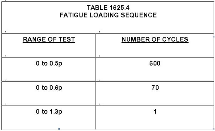
1. Each cycle shall have minimum duration of 1 second and a maximum duration of 3 seconds and must be
performed in a continuous manner.
2. p = the design wind load for the height and location, when the assembly will be used. For wall and roof
components, shape factors given in ASCE 7 shall be used.
Assemblies shall be tested with no resultant failure or distress and shall have a recovery of at least 90 percent over maximum deflection.
Any cladding assembly not incorporated into the Florida Building Code, Building after successfully completing the impact test outlined in Section 1626, shall be subject to fatigue loading testing and shall obtain product approval by the building official.
SECTION 1626
1626.1 -All parts or systems of a building or structure envelope such as, but not limited, to exterior walls, roof, outside doors, skylights, glazing and glass block shall meet impact test criteria or be protected with an external protection device that meets the impact test criteria. Test procedures to determine resistance to wind-borne debris of wall cladding, outside doors, skylights, glazing, glass block, shutters and any other external protection devices shall be performed in accordance with this section.
Exception: The following structures or portion of structures shall not be required to meet the provisions of this section:
- a. Roof assemblies for screen rooms, porches, canopies, etc. attached to a building that do not breach the exterior wall or building envelope and have no enclosed sides other than screen.
- b. Soffits, soffit vents and ridge vents. Size and location of such vents shall be detailed by the designer and shall not compromise the integrity of the diaphragm boundary.
- c. Vents in a garage with four or fewer cars. Size and location of such vents shall be detailed by the designer and shall not exceed the minimum required area by more than 25 percent.
- d. Exterior wall or roof openings for wall-or roof-mounted HVAC equipment.
- e. Openings for roof-mounted personnel access roof hatches.
- f. Storage sheds that are not designed for human habitation and that have a floor area of 720 square feet (67 m 2) or less are not required to comply with the mandatory windborne debris impact standards of this code.
- g. Louvers as long as they properly considered ASCE 7 in the design of the building.
- h. Buildings and structures for marinas, cabanas, swimming pools, solariums and greenhouses.
1626.2 -LARGE MISSILE IMPACT TESTS
1626.2.1 –This test shall be conducted on three test specimens.
This test shall be applicable to the construction units, assemblies and materials to be used up to and including 30 feet (9.1 m) in height in any and all structures.
1626.2.2 -The test specimens shall consist of the entire assembled unit, including frame and anchorage as supplied by the manufacturer for installation in the building, or as set forth in a referenced specification, if applicable. Fasteners used in mounting the test specimen shall be identical in size and spacing to what is used in field installations.
1626.2.3 -The large missile shall be comprised of a piece of timber having nominal dimensions of 2 inches by 4 inches (51 mm by 102 m) weighing 9 pounds (4.1 kg).
1626.2.4 -The large missile shall impact the surface of each test specimen at a speed of 50 feet per second
(15.2 m/s).
1626.2.5 -Each test specimen shall receive two impacts except as noted in Sections 1626.2.5.1 and 1626.2.5.2, the first within a 5-inch (127 mm) radius circle having its center on the midpoint of the test specimen and the second within a 5-inch (127 mm) radius circle in a corner having its center in a location 6 inches (152 mm) away from any supporting members.
1626.2.5.1 -For window, glass block, fixed glass and skylight assemblies, both impacts shall be to glass or other glazing infill. For test specimens with more than one light of glass, a single light closest to the center of the assembly shall be selected and impacted twice in accordance with Section 1626.2.5. If a light of glass is sufficiently small to cause the 5-inch (127 mm) radius circle to overlap, two separate lights shall be impacted one time each.
1626.2.5.1.1 -For window, fixed glass and skylight assemblies comprised of different glass
thickness, types of glass or different types of glazing infill, each separate thickness or type shall be
impacted twice in accordance with Section 1626.2.5.
1626.2.5.2 -For doors, wall cladding and external protection devices, both impacts shall be to the thinnest section through the assembly. For doors, wall cladding and external protection devices with horizontal and/or vertical bracing, both impacts shall be within a single area that is not reinforced and shall be in accordance with Section 1626.2.5.
1626.2.5.2.1 -For doors with glass, the glass shall be impacted twice and the thinnest section
through the assembly that is not glass shall be impacted twice in accordance with Section 1626.2.5.
1626.2.6 -In the case of glazing, if the three test specimens that comprise a test successfully reject the two missile impacts, they shall then be subjected to the cyclic pressure loading defined in Table 1626.
1626.2.6.1 -If external protection devices are employed to protect windows, fixed doors or skylights, they must resist the large missile impacts specified in Sections 1626.2.3 and 1626.2.4 without deformations which result in contact with the windows, fixed glass, glass block, and doors or skylights they are intended to protect.
1626.2.6.2 -If external protection devices are not designed to be air tight, following the large missile
impact test, they must resist an application of force corresponding to those listed in Table 1625.4 (fatigue
load testing) without detaching from their mountings. The acting pressure cycles shall be simulated with
loads applied through a mechanical system attached to the shutter specimen to apply uniformly around
the shutter perimeter a force equal to the product of the required pressure and the area of the shutter
specimen.
1626.2.7 -If air leakage through the test specimen is excessive, tape may be used to cover any cracks and joints through which leakage is occurring. Tape shall not be used when there is a probability that it may significantly restrict differential movement between adjoining members. It is also permissible to cover both sides of the entire specimen and mounting panel with a single thickness of polyethylene film no thicker than 0.050mm(2 mils). The technique of application is important in order that the full load is transferred to the specimen and that the membrane does not prevent movement or failure of the specimen. Apply the film loosely with extra folds of material at each corner and at all offsets and recesses. When the load is applied, there shall be no fillet caused by tightness of plastic film.
1626.2.8 -A particular system of construction shall be deemed to comply with this recommended practice if three test specimens reject the two missile impacts without penetration and resist the cyclic pressure loading with no crack forming longer than 5 inches (127 mm) and 1/16 inch (1.6 mm) wide through which air can pass.
1626.2.9 -If only one of the three test specimens in a test fails to meet the above listed criteria, one retest of this system of construction (another test sequence with three specimens) shall be permitted.
1626.3 -SMALL MISSILE IMPACT TEST
1626.3.1 -This test shall be conducted on three test specimens.
This test shall be applicable to the construction units, assemblies, and materials to be used above 30 feet (9.1 m) in height in any and all structures.
1626.3.2 -Each test specimen shall consist of the entire assembled unit, including frame and anchorage as supplied by the manufacturer for installation in the building, or as set forth in a referenced specification, if applicable. The fasteners used in mounting the test specimen shall be identical in size and spacing to those to be used in field installations.
1626.3.3 -The missiles shall consist of solid steel balls each having a mass of 2 grams (0.07 oz) (+/-5 percent) with a 5/16-in. (7.9 mm) nominal diameter.
1626.3.4 -Each missile shall impact the surface of each test specimen at a speed of 130 feet per second (40 m/s).
1626.3.5 -Each test specimen shall receive 30 small missile impacts except as noted in Sections 1626.3.5.1
and 1626.3.5.2 delivered in groups of 10 at a time: the first 10 distributed uniformly over a 2 square foot area located at the center of the test specimen, the second 10 distributed uniformly over a 2 square foot
area located at the center of the long dimension of the specimen near the edge, and the third 10
distributed uniformly over a 2 square foot area located at a corner of the specimen.
1626.3.5.1 -For window and skylight assemblies, all impacts shall be to glass or other glazing infill. For
test specimens with more than one light of glass, a single light closest to the center of the assembly shall
be selected and impacted in accordance with Section 1626.3.5. If a light of glass is sufficiently small to
cause the 5-inch (127 mm) radius circles to overlap, separate lights may be impacted; however, there
must be a total of 30 impacts within the assembly.
1626.3.5.1.1 –For window, fixed glass and skylight assemblies comprised of glass with different
thickness, types of glass or different types of glazing infill, each separate thickness or type shall be
impacted in accordance with Section 1626.3.5.
1626.3.5.2 -For doors, wall cladding and external protection devices, all impacts shall be to the thinnest
section, through the assembly. For doors, wall cladding and external protection devices with horizontal
and/or vertical bracing, all impacts shall be within a single area that is not reinforced and shall be
impacted in accordance with Section 1626.3.5.
1626.3.5.2.1 -For doors with glass, the glass shall be impacted in accordance with Section 1626.3.5 and the thinnest section through the assembly that is not glass shall be impacted in accordance with Section 1626.3.5.
1626.3.6 -In the case of glazing, after completion of the small missile impacts, each test specimen shall then be subjected to the cyclic pressure loading defined in Table 1626.
1626.3.6.1 -If external protection devices are employed to protect windows, doors or skylights, they must
resist the small missile impacts specified in Sections 1626.3.3 and 1626.3.4 without deformations that
result in contact with the windows, glass, doors or skylights they are intended to protect.
1626.3.6.2 -If external protection devices are not designed to be air tight, following the small missile
impact test, they must resist an application of force corresponding to those listed in Table 1625.4 (fatigue
load testing) without detaching from their mountings. The acting pressure cycles shall be simulated with
loads applied through a mechanical system attached to the shutter specimen to apply uniformly around
the shutter perimeter a force equal to the product of the required pressure and the area of the shutter
specimen.
1626.3.7 -If air leakage through the test specimen is excessive, tape may be used to cover any cracks and joints through which leakage is occurring. Tape shall not be used when there is a probability that it may significantly restrict differential movement between adjoining members. It is also permissible to cover both sides of the entire specimen and mounting panel with a single thickness of polyethylene film no thicker than 0.050mm(2 mils). The technique of application is important for the full load to be transferred to the specimen and to insure the membrane does not prevent movement or failure of the specimen. Apply the film loosely with extra folds of material at each corner and at all offsets and recesses. When the load is applied, there shall be no fillet caused by tightness of plastic film.
1626.3.8 -A particular system of construction shall be deemed to comply with this test if three test specimens reject the small missile impacts without penetration and resist the cyclic pressure loading with no crack forming longer than 5 inches (127 mm) and 1/16 inch (1.6 mm) in width through which air can pass.
1626.3.9 -If only one of the three test specimens in a test fails to meet the above listed criteria, one retest of the system (another test sequence with three specimens) of construction shall be permitted.
1626.4 -CONSTRUCTION ASSEMBLIES DEEMED TO COMPLY WITH SECTION 1626
- 1. Exterior concrete masonry walls of minimum nominal 8-inch (203 mm) thickness, constructed in accordance with Chapter 21 (High-Velocity Hurricane Zones) of this code.
- 2. Exterior frame walls or gable ends constructed in accordance with Chapter 22 and Chapter 23 (High-Velocity Hurricane Zones) of this code, sheathed with a minimum 19/32-inch (15 mm)CD exposure 1 plywood and clad with wire lath and stucco installed in accordance with Chapter 25 of this code.
- 3. Exterior frame walls and roofs constructed in accordance with Chapter 22 (High-Velocity Hurricane Zones) of this code sheathed with a minimum 24-gage rib deck type material and clad with an approved wall finish.
- 4. Exterior reinforced concrete elements constructed of solid normal weight concrete (no voids), designed in accordance with Chapter 19 (High-Velocity Hurricane Zones) of this code and having a minimum 2-in. (51 mm) thickness.
- 5. Roof systems constructed in accordance with Chapter 22 or Chapter 23 (High-Velocity Hurricane Zones) of this code, sheathed with a minimum 19/32-inch (15 mm) CD exposure 1 plywood or minimum nominal 1-inch (25 mm) wood decking and surfaced with an approved roof system installed in accordance with Chapter 15 of this code. All connectors shall be specified by the building designer of record for all loads except impact.
TABLE 1626 CYCLIC WIND PRESSURE LOADING
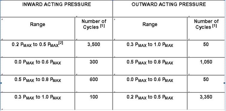
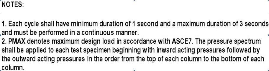
Questions & Answers
The questions and answers below came directly from Chapter 4 of “Guide to the Use of the Wind Load Provisions of ASCE 7-02” by Kishor C. Mehta and James M. Delahay (as found on the Internet):
1. Is it possible to obtain larger scale maps of basic wind speeds (see Figures 6-1, 6-1a, 6-1b, and 6-1c) so that the locations of the wind speed contours can be determined with greater accuracy?
No. The wind speed contours in the hurricane-prone region of the United States are based on hurricane wind speeds from Monte Carlo simulations and on estimates of the rate at which hurricane wind speeds attenuate to 90 mph following landfall. Because the wind speed contours of these figures represent a consensus of the ASCE 7 Task Committee on Wind Loads, increasing the map scale would do nothing to improve their accuracy.
2. IBC Figure 1609 gives the 3-s wind speed at the project location. However, according to the Notes, Figure 1609 is for Exposure C. If the project location is Exposure B, what is the proper wind speed to use?
The basic wind speed in IBC Figure 1609 or ASCE 7-02 is defined as a 3-s gust wind speed at 33 ft above ground for Exposure Category C, which is the standard measurement. The velocity pressure exposure coefficient, K , adjusts the wind speed for exposure and height above ground. However, for simplicity the coefficient is applied in the pressure equation, thus adjusting pressure rather than wind speed. Use of K z adjusts the pressures from Exposure C to Exposure B.
3. If the design wind loads are to be determined for a building that is located in a special wind region (shaded areas) in Figures 6-1, 6-1a, 6-1b, and 6-1c, what basic wind speed should be used?
- The purpose of the special wind regions in these figures is to alert the designer to the fact that there are regions in which wind speed anomalies are known to exist. Wind speeds in these regions may be substantially higher than the speeds indicated on the map, and the use of regional climatic data and consultations with a wind engineer or meteorologist are advised.
In the design of the main wind force-resisting systems (MWFRS), the provisions of Figure 6-6 apply to enclosed or partially enclosed buildings of all heights. The provisions of Figure 6-10 apply to enclosed or partially enclosed buildings with mean roof height less than or equal to 60 ft. Does this mean that either figure may be used for the design of a low-rise MWFRS?
Figure 6-6 may be used for buildings of all heights, whereas Figure 6-10 applies only to low-rise buildings. Section
6.2 defines low-rise buildings to comply with mean roof height h or = 60 ft and h not to exceed least horizontal dimensions. Pressure coefficients for low-rise buildings given in Figure 6-10 represent “pseudo” loading conditions enveloping internal structural reactions of total uplift, total horizontal shear, bending moment, etc. (see Section C6.5.11). Thus, they are not real wind-induced loads. These loads work adequately for buildings of the shapes shown in Figure 6-10, but they become questionable when extrapolated to other shapes.
5. Do I consider a tilt-up wall system to be components and cladding (C&C) or MWFRS or both?
Both. Depending on the direction of the wind, a tilt-up wall system must resist either MWFRS forces or C&C forces. In the C&C scenario, the elements receive the wind pressure directly and transfer the forces to the MWFRS in the other direction. When a tilt-up wall acts as a shear wall, it is resisting forces of MWFRS. Because the wind is not expected to blow from both directions at the same time, the MWFRS forces and C&C forces are analyzed independently from each other in two different load cases. This is also true of masonry and reinforced-concrete walls.
6. Section 6.1.4.1 provides for a minimum wind pressure of 10 lb/ft 2 multiplied by the area of the building or structure projected onto a vertical plane normal to the assumed wind direction of MWFRS. Does this provision apply to low-rise buildings?
It should. There was some confusion in ASCE 7-98 provisions for low-rise buildings where it was difficult to interpret application of loads on building frames using the two cases of loads at each corner. Figure 6-10 in ASCE 7-02 clarifies with illustrative sketches the application of loads on low-rise buildings, and only one table of pressure coefficients is provided. In addition, Note 6 is added to account for minimum total horizontal shear, although this provision does not guarantee minimum 10 psf on the projected area of the building.
7. When can I use the one-third stress increase specified in some material standards?
When using the loads or load combinations specified in ASCE 7-02, no increase in allowable stress is permitted except when the increase is justified by the rate of duration of load (such as duration factors used in wood design). Instead, load combination #6 from Section 2.4.1 of ASCE 7-02 was added for the case when wind load and another transient load are combined. This load combination applies a 0.75 factor to the transient loads ONLY (not to the dead load). The 0.75 factor applied to the transient loads accounts for the fact that it is extremely unlikely that two maximum events will happen at the same time.
8. Why can the wind directionality factor (Kd) only be used with the load combinations specified in Sections 2.3 and 2.4 of ASCE 7-02?
In the strength design load combinations provided in previous editions of ASCE 7 (ASCE 7-95 and earlier), the
1.3 factor for wind included a “wind directionality factor” of 0.85. In ASCE 7-98, the loading combinations used
1.6 instead of 1.3 (approximately equals 1.6 x 0.85), and the directionality factor is included in the equation for velocity pressure. Separating the directionality factor from the load combinations allows the designer to use specific directionality factors for each structure and allows the factor to be revised more readily when new research becomes available.
What exposure category should I use for the MWFRS if the terrain around my site is Exposure B, but there is a large parking lot directly next to one of the elevations?
Section 6.5.6 of ASCE 7-02 provides general definitions of Exposures B, C, and D; however, the designer must refer to the Commentary for a detailed explanation for each exposure. The exposure depends on the size of the parking lot, its size relative to the building, and the number and type of obstructions in the area. Section C6.5.6 of the Commentary includes a formula (Eq. C6-2) that will help the designer determine if the terrain roughness is sufficient to be categorized as Exposure B. Note that, for Exposure B, the fetch distance is 2,630 ft or 10 times the structure’s height, whichever is greater. Also note that the Commentary provides suggestions for determining the “upwind fetch surface area.”
For clearings such as parking lots, wide roads, road intersections, underdeveloped lots, and tree clearings, the Commentary provides a rational procedure and an example to interpolate between Exposure B and C; the designer is encouraged to use this procedure.
10.
What pressure coefficients should be used to reflect contributions for the underside (bottom) of the roof
overhangs and balconies?
Sections 6.5.11.4.1 and 6.5.11.4.2 specify pressure coefficients to be used for roof overhangs to determine loads for MWFRS and C&C, respectively. No specific guidance is given for balconies, but use of the loading criteria for roof overhangs should be adequate.
11.
If the mean roof height, h, is greater than 60 ft with a roof geometry that is other than flat roof, what pressure coefficients are to be used for roof C&C design loads?
Section 6.5.12.4.3 permits use of pressure coefficients of Figures 6-11 through 6-16 provided the mean roof height h 90 ft, the height-to-width ratio is 1 or less, and Eq. 6-22 is used.
Note 6 of Figure 6-17 permits use of coefficients of Figure 6-11 when the roof angle 0 > 10°.
12.
Under what conditions is it necessary to consider speed-up due to topographic effects when calculating wind loads?
Section 6.5.7 of the Standard requires the calculation of the topographic factor, K zt, for buildings and other structures sited on the upper half of isolated hills or escarpments located in Exposures B, C, or D where the upwind terrain is free of such topographic features for a distance of at least 100 h or 2 mi, whichever is smaller, as measured from the crest of the topographic feature. K zt need not be calculated when the height, H, is less than 15 ft in Exposures D and C, or less than 60 ft in Exposure B. In addition, K zt need not be calculated when H and Lh is less than 0.2. h and Lh are defined in Figure 6-4. The value of K zt is never less than 1.0.
13.
What constitutes an open building? If a process plant has a three-story frame with no walls but with a lot of equipment inside the framing, is this an open building?
An open building is a structure in which each wall is at least 80% open (see Section 6.2). Yes, this three-story frame would be classified as an open building, or as “other” structure. In calculating the wind force, F, appropriate values of C and A would have to be assigned to the frame and to the equipment inside.
ff
14.
When is a gable truss in a house part of the MWFRS? Should it also be designed as a C&C? What about
individual members of a truss?
Roof trusses are considered to be components since they receive load directly from the cladding. However, since a gable truss receives wind loads from more than one surface, which is part of the definition for MWFRS, an argument can be made that the total load on the truss is more accurately defined by the MWFRS loads. A common approach is to design the members and internal connections of the gable truss for C&C loads, while using the MWFRS loads for the anchorage and reactions. When designing shear walls or cross-bracing, roof loads can be considered an MWFRS.
In the case where the tributary area on any member exceeds 700 ft 2, Section 6.5.12.1.3 permits it to be considered a MWFRS. Even when considered a MWFRS under this provision, the top chord members of a gable truss would have to follow rules of C&C if they receive load directly from the roof sheathing.
15.
Flat roof trusses are 30 ft long and are spaced on 4-ft centers. What effective wind area should be used to
determine the design pressures for the trusses?
Roof trusses are classified as C&C since they receive wind load directly from the cladding (roof sheathing). In this case, the effective wind area is the span length multiplied by an effective width that need not be less than one-third the span length or (30)(30/3) = 300 ft 2. This is the area on which the selection of GC p should be based. Note, however, that the resulting wind pressure acts on the tributary area of each truss, which is (30)(4) = 120 ft 2.
16.
Roof trusses have a clear span of 70 ft and are spaced 8 ft on center. What effective wind area should be used to determine the design pressures for the trusses?
Following the approach of question #15, above, the effective wind area is (70)(70/3) = 1,633 ft 2. The tributary area of the truss is (70)(8) = 560 ft 2, which is less than the 700-ft 2 area required by Section 6.5.12.1.3 to qualify for design of the truss using the rules for MWFRS. The truss is to be designed using the rules for C&C, and the wind pressure corresponding to an effective wind area of 1,633 ft2 is to be applied to the tributary area of 560 ft .
17.
Metal decking consisting of panels 20 ft long and 2 ft wide is supported on purlins spaced 5 ft apart. Will the effective wind area be 40 ft2 for the determination of pressure coefficients?
Although the length of a decking panel is 20 ft, the basic span is 5 ft. According to the definition of effective wind area, this area is the span length multiplied by an effective width that need not be less than one-third the span length. This gives a minimum effective wind area of (5)(5/3) = 8.3 ft 2. However, the actual width of a panel is 2 ft, making the effective wind area equal to the tributary area of a single panel, or (5)(2) = 10 ft 2. Therefore, GCp would be determined on the basis of 10 ft2 of effective wind area, and the corresponding wind load would be
2
applied to a tributary area of 10 ft2. Note that GCp is constant for effective wind areas less than 10 ft .
18.
A masonry wall is 12 ft in height and 80 ft long. It is supported at the top and at the bottom. What effective wind area should be used in determining the design pressure for the wall?
For a given application, the magnitude of the pressure coefficient, GC p, increases with decreasing effective wind area. Therefore, a very conservative approach would be to consider an effective wind area with a span of 12 ft and a width of 1 ft, and design the wall element as C&C. However, the definition of effective wind area states that this area is the span length multiplied by an effective width that need not be less than one-third the span length. Accordingly, the effective wind area would be (12)(12/3) = 48 ft2.
19.
If a monoslope roof over an open building is virtually flat, what force coefficients from Figure 6-18 should be used?
A requirement for the use of Figure 6-18 is that the wind shall be assumed to deviate plus or minus 10 from the horizontal. Accordingly, the values of Cf corresponding to a roof angle of 10 should be used. The wind forces may be directed either inward or outward, and both cases should be checked.
20.
A trussed tower of 10 x 10-ft 2 cross section consists of structural angles forming basic tower panels 10 ft high.
The solid area of the face of one tower panel projected on a plane of that face is 22 ft 2. What force coefficient, Cf , should be used to calculate the wind force? What would the force coefficient be for the same tower fabricated of rounded members and having the same projected solid area? What area should be used to obtain the wind force per foot of tower height acting (1) normal to a tower face, and (2) along a tower diagonal?
The gross area of one panel face is (10)(10) = 100 ft 2, and the solidity ratio is 22/100 = 0.22. For a tower of square cross section, the force coefficient from Figure 6-22 is as follows:
Cf = (4)(0.22)2 -(5.9)(0.22) + 4.0 = 2.90
For rounded members, the force coefficient may be reduced by the factor
(0.51)(0.22)2 + 0.57 = 0.59
Thus, the force coefficient for the same tower constructed of rounded members with the same projected area would be
Cf = (0.59)(2.90) = 1.71
The area, A , used to calculate the wind force per foot of tower height is 22/10 = 2.2 ft 2 for all wind directions.
f
21.
In calculating the wind forces acting on a trussed tower of square cross section (see Figure 6-22), should the force coefficient, Cf , be applied to both the front and the back (windward and leeward) faces of the tower?
No. The calculated wind forces are the total forces acting on the tower. The force coefficients given in Figure 6-22 include the contributions of both front and back faces of the tower, as well as the shielding effect of the front face on the back face.
22.
If the pressure or force coefficients for various roof shapes (e.g., a canopy) are not given in ASCE 7-02, how can
the appropriate wind forces be determined for these shapes?
With the exception of pressure or force coefficients for certain shapes, parameters such as V, I, K , K , and G are
z zt
given in ASCE 7-02. It is possible to use pressure or force coefficients from the published literature provided these coefficients are used with care. Mean pressure or force coefficients from other sources can be used to determine wind loads for MWFRS. However, it should be recognized that these coefficients might have been obtained in wind tunnels that have smooth, uniform flows as opposed to more proper turbulent boundary-layer flows. Pressure coefficients for components and cladding obtained from the literature should be adjusted to the 3-s gust speed, which is the basic wind speed adopted by ASCE 7-02.
23.
Section 6.2 of the Standard provides definitions of glazing, impact resistant; impact-resistant covering; and wind-borne debris regions. To be impact resistant, the Standard specifies that the glazing of the building envelope must be shown by an approved test method to withstand the impact of wind-borne missiles likely to be generated during design winds. Where does one find information on appropriate test methods?
Section 6.7 of the Standard refers to two ASTM standards. These standards give test method and performance criteria of glazing, doors, and shutters when impacted by wind-borne debris.
24.
The Standard does not provide for across-wind excitation caused by vortex shedding. How can one determine when vortex shedding might become a problem?
Vortex shedding is almost always present with bluff-shaped cylindrical bodies. Vortex shedding can become a problem when the frequency of shedding is close to or equal to the frequency of the first or second transverse of the structure. The intensity of excitation increases with aspect ratio (height-to-width or length-to-breadth) and decreases with increasing structural damping. Structures with low damping and with aspect ratios of 8 or more may be prone to damaging vortex excitation. If across-wind or torsional excitation appears to be a possibility, expert advice should be obtained.
25.
If high winds are accompanied by rain, will the presence of raindrops increase the mean density of the air to the point where the wind loads are affected?
No. Although raindrops will increase the mean density of the air, the increase is small and may be neglected. For example, if the average rate of rainfall is 5 in./h, the average density of raindrops will increase the mean air density by less than 1%.
26.
What wind loads do I use during construction?
ASCE 7 does not address wind loads during construction. Construction loads are specifically addressed in the standard SEI/ASCE 37-01, Design Loads on Structures during Construction.
27.
Can the pressure/force coefficients given in ASCE 7-02 be used with the provisions of ASCE 7-88, 7-93, 7-95, or 7-98?
Yes, in a limited way. ASCE 7-88 (and 7-93) used the fastest-mile wind speed as the basic wind speed. With the adoption of the 3-s gust speed starting with ASCE 7-95, the values of certain parameters used in the determination of wind forces have been changed accordingly. The provisions of ASCE 7-88 and 7-02 should not be interchanged. Coefficients in ASCE 7-95, 7-98, and 7-02 are consistent; they are related to 3-s gust speed.
28.
Is it possible to determine the wind loads for the design of interior walls?
The Standard does not address the wind loads to be used in the design of interior walls or partitions. A conservative approach would be to apply the internal pressure coefficients GCpi = ± 0.18 for enclosed buildings and GCpi = ± 0.55 for partially enclosed buildings. Post-disaster surveys have revealed the failure of interior walls when the building envelope has been breached.
More questions and answers:
Does the design of my house affect the design wind pressures on my garage door?
Yes. The least overall horizontal plan dimension of the structure as well as the mean roof height affect the design wind pressures on the structure.
How can I determine the wind speed requirements for my location?
The American Society of Civil Engineers (ASCE) has developed standards covering wind loads on buildings and other structures. This is the base standard for most wind provisions used in U.S. building codes. The basic wind speed maps from ASCE7-02 can help an individual to determine the proper wind speed delineation zones for their area. In addition, some states, such as Florida, provide a listing of wind speed maps by county. For the specific requirements for your area, contact your local building official.
How do I know if my door is compliant with the wind requirements of the Florida Building Code?
The Florida Building Code has specific design pressure requirements for garage doors (Table 1606.2E). Suppliers go through the Florida Building Commission Product Approval system for many of their doors. Additional information about the Florida code can be found through the Florida Building Commission.
I am installing a new wind loaded garage door in an older home. How do I know if the building frame can support the wind loads from the garage door?
A qualified design professional such as an architect, structural engineer, or contractor should be consulted to determine if the building frame is adequate to support the loads.
I live in a 120 mph wind speed region. How do I determine what wind pressures I need?
Please contact your local building official or a registered architect or structural engineer for the specific requirements in your area. Ultimately, the engineer on record for the structure should provide the wind pressure requirements for all openings.
What effect do windows in a garage door have on design wind pressures?
Windows have no effect on the design wind pressures except in wind-borne debris regions. In wind-borne debris regions, all windows (including windows in a garage door) must be impact resistant or protected with an impact resistant covering unless the structure is designed as a partially enclosed structure.
What is the difference between wind speed and wind pressure? Why can’t you just supply doors based on wind speed alone, such as a 120 mph door?
Wind speed is a velocity measured in miles per hour (mph). Wind pressure is a force measured in pounds per square foot (psf). Wind speed alone cannot be used to determine the wind pressures on a structure. Wind speed is one of many variables used in calculating design wind pressures that take into account the structure configuration and site location.
Does the direction in which a door is facing affect the design wind pressures?
No. Wind can blow in any direction. Wind load design takes into consideration wind acting directly towards and away from the garage door.
I have an older door that is not a wind loaded door. Can I add reinforcement to my door to make it stronger?
A wind loaded garage door is designed with specific components, such as track, jamb brackets, hinges, rollers and reinforcing struts that meet designated design wind pressures. All of these components, along with the door sections, comprise a complete wind resistive system.
You should not add components to a door that are not part of the original door installation. Adding reinforcement to the door does not necessarily increase the wind resistance of the door. It may also be extremely dangerous, because the components may add weight that can overload the counterbalance system resulting in failure and possible injury.
I have heard of active (post) systems. What are they and are they acceptable by local building officials?
Active systems are any type of reinforcing system used on a garage door that requires action by the homeowner or end user to resist high wind events. Most jurisdictions in hurricane-prone regions accept active systems, but some do not. Check with your local building official for requirements in your area.
I have heard the term Exposure Category. What does this mean?
An Exposure Category (B, C, or D) is a condition that adequately reflects the characteristics of ground surface irregularities for the site where a structure is located. The Exposure Category is used in calculating the required design wind pressures for a structure, with exposure B yielding the lowest wind pressures and exposure D yielding the highest.
Exposure B applies to urban and suburban areas, wooded areas or other terrain with numerous closely spaced obstructions having the size of single-family dwellings or larger. Exposure B is typically associated with site locations in a residential subdivision. Most site locations are assumed to be Exposure B unless the site meets the definition of another type of exposure.
Exposure C applies to open terrain with scattered obstructions having heights generally less than 30 feet extending more than 1,500 feet from the building site. Exposure C includes flat open country, grasslands, and shorelines in hurricane-prone regions.
Exposure D applies to flat, unobstructed areas exposed to wind flowing over open water (excluding shorelines in hurricane-prone regions) for a distance of at least 1 mile. Exposure D includes shorelines in inland waterways, the Great Lakes, and coastal areas of California, Oregon, Washington, and Alaska. Exposure D extends inland from the shoreline a distance of 1,500 feet or 10 times the height of the building or structure, whichever is greater.
I have heard the term partially enclosed structure. What does that mean and do normal doors meet the requirements for a partially enclosed structure?
Partially enclosed structures are structures that are assumed to have a certain percentage of openings (such as broken windows) during a storm event. Under this assumption, the pressure inside a structure increases dramatically. This causes an increase in the design pressures on exterior walls as well.
Some doors do meet these requirements, but the required design pressures for a partially enclosed structure are substantially higher than for an enclosed structure.
I need to replace my existing garage door. Do I have to get a wind loaded door? Do I have to have a permit?
You will need to contact your local building official. The local authority has jurisdiction and makes the sole
determination for all permitting and wind load requirements.
What is the difference between design pressures and test pressures?
Design pressures are the pressures required by code that a door is designed to withstand and are calculated using variables, taking into account wind speed, structure configuration, and site location. Test pressures are the pressures that a door has been tested to in controlled laboratory conditions. Test pressures for garage doors have a 50% safety factor, making test pressures one and a half times higher than design pressures.
Why are both positive and negative wind pressures required?
Wind can blow in any direction including away from a wall surface. In fact, negative wind pressures have a
larger magnitude than positive wind pressures.
Conclusions
Kisshnor C. Mehta, PE is the lead author of the “Guide to the Use of the Wind Load Provisions of ASCE 7-02” and is the former Director of the Wind Science and Engineering Research Center at Texas Tech University. He served as Chairman of the ASCE Task Committee on Wind Loads.
James Delahay, P.E. is president/CEO of LBYD Inc., a consulting firm in Birmingham, Alabama.
Wind Loading
The purveyors of products will always want their product to be the only one that meets code, so they try to get the codes changed to their benefit. The code writers want their product implemented, and every year we will get changes. New methods are dreamed up to test things, and politics has its way.
This is not the end, by any means. For example:
Sofia M. C. Diniz, Member, ASCE (Associate Professor, Dept. of Structural Engineering, Federal Univ. of Minas Gerais, Belo Horizonte, Brazil.), and Emil Simiu, Fellow, ASCE have written a paper that opens up even more questions.
Document type: Journal Paper
Abstract:
Database-assisted design (DAD) for wind results in structures with reduced material consumption and failure risks, i.e., in improved safety and sustainability. The paper presents a DAD-compatible probabilistic procedure for estimating: (1) Wind effects corresponding to any mean recurrence interval of the wind speeds, and (2) wind-load factors. Unlike the ASCE 7 Standard and earlier structural reliability estimates, the procedure accounts for the inherent randomness in the estimation of peaks and for relevant wind-related knowledge uncertainties. On the basis of a selection of uncertainty parameters believed to be reasonable, it is concluded that: (1) The extreme wind speed distribution type significantly affects the estimates of the load factors. Our estimates, based on the Extreme Value Type III Reverse Weibull distribution, yield load factors consistent with values specified in the ASCE 7 Standard.in contrast to estimates published in the 1980’s. (2) The variability of the ratio between wind speeds averaged over different time intervals can significantly affect the estimated wind-load factor. (3) An increase in size of the extreme wind data set from, say, 30 to 50 years, has a marginal effect on load factor estimates. (4) For low-rise buildings in open terrain, wind-load factors are typically affected weakly by even large uncertainties with respect to terrain roughness length. Additional research on the effect of terrain roughness uncertainties for buildings in built-up terrain may require an expansion of the aerodynamic databases currently available. It is noted that consideration of uncertainties in isolation, as commonly performed by some analysts and wind tunnel operators, especially for peak effects estimation, can be misleading; for structural applications, uncertainties need to be considered collectively.
And, the feds have done some research:
U.S. Department of Housing and Urban Development
(Click above to view their research program … excerpt follows:)
“The objective of this research was to provide needed data on the fragility (i.e., impact magnitude vs. glass breakage probability) of typical residential glass using field-observed and standardized missile types representing wind-borne debris. In this experimental study, representative sources of debris hazards, such as pieces of roof shingles and nominal 2 in. by 4 in. dimension lumber (hereafter referred to as a ‘2×4’) were used to impact “standard” (i.e., non-impact resistant) glass, namely annealed glass. The test matrix included both 3/32-in. and 5/32-in. glass thickness tested at 1:1 and 2:1 aspect ratios (2 ft x 2 ft and 2 ft x 4 ft panels). Impact speed was varied as necessary to characterize fragility (i.e., glass breakage probability vs. impact magnitude). In addition, the response of annealed glass to multiple impacts was investigated. Representations of impact magnitude using kinetic energy and momentum are also compared with respect to the ability to predict glass behavior or fragility.
From this work, it is anticipated that wind-borne debris hazards and standardized performance criteria for wind-borne debris protection of glazing in residential buildings will be improved or at least better understood.”
In other words, they found that glass breaks when you hit it! In addition, others have their own ideas:
Prediction of Local Exterior Wind Pressures from Wind Tunnel Studies Using a Time History Analysis Approach
Scott L. Gamble, Roger J. Miltenburg, Michael D. Cicci, Marco Accardo
Rowan Williams Davies & Irwin Inc. (RWDI), Guelph, Ontario, Canada
Abstract
Wind tunnel tests are commonly used to predict local exterior wind pressures acting on the facade of a building. For design purposes, the local peak pressure coefficients obtained from a wind tunnel test must be combined with meteorological data on the gradient winds over the site taking into account the joint probability of wind speed and direction. Traditionally, a Weibull distribution has been used to represent the statistical distribution of hourly wind speed data from an anemometer station or, in the case of hurricane/typhoon areas, from a Monte Carlo simulation as well. Until now, the peak pressure coefficients have been combined with the statistical wind climate model using the Aupcrossing method” to predict the local wind pressures acting on the building. This paper presents an alternative method of predicting local exterior wind pressures by performing a time history analysis of the combined meteorological readings (and simulated data where applicable) and the peak pressure coefficients measured in a wind tunnel. The time history analysis approach is described and predicted peak design wind pressures obtained from this approach are compared to the traditional method of Weibull fitting and upcrossing analysis by evaluating test cases on some sample buildings.
1. Introduction
1.1 Wind Tunnel Testing
Wind tunnel testing has been an invaluable resource for designers of proposed buildings and structures, where a balance of safety and cost is desired, by providing an accurate prediction of wind loading for design. In the case of the design of the facade of a building, wind tunnel tests can be conducted to predict local exterior wind pressures acting on the exterior envelope of a building. In this approach, the local peak pressure coefficients obtained from a wind tunnel test are measured on a direction-by-direction basis (typically for 36 wind directions in 10E increments), at many locations on a scale model of the building exposed to an approaching wind. In most cases, the study building model is constructed in detail at a scale of approximately 1:400 and the surroundings within a full scale radius of around 450m or more are also modeled in detail. The study building model and its surroundings are tested in a boundary layer wind tunnel where the mean velocity profile and turbulence properties of the winds approaching the study site are simulated.
EXAMPLE:
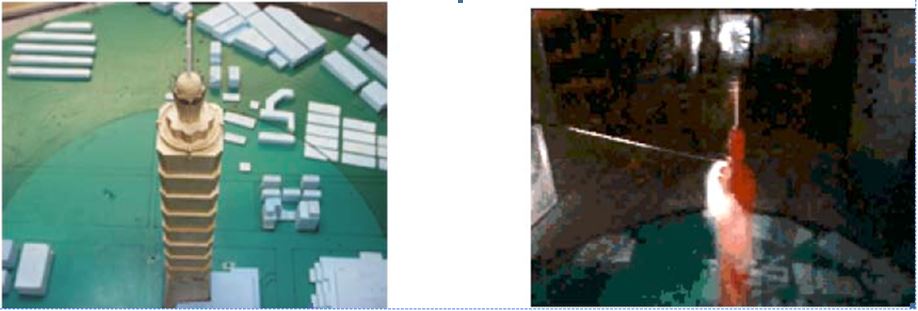
Model of a building and surrounding area Wind tunnel testing in progress
During the wind tunnel test, the peak negative and peak positive pressures are measured at each local pressure measurement location along with the mean pressures and the root-mean-square pressure fluctuations. Irwin[1] provides a general description of wind tunnel pressure model testing techniques. The measured pressure data are then converted to pressure coefficients based on the mean dynamic pressure of the approaching wind at gradient height, which is typically taken to be a full scale height of 600m above ground in strong winds.
1.2 Local Meteorology
For design purposes, the local peak pressure coefficients obtained from a wind tunnel test must be combined with meteorological data on the gradient winds over the site. Since winds do not generally approach from all directions with equal frequency, but tend to blow strongly from a few preferred directions, it is desirable when predicting the wind pressures to take into account the joint probability of wind speed and direction. This probability is generally determined from observed data in the form of hourly records of surface wind speed and direction measured at an airport anemometer station nearby to the study building site. The Weibull distribution has been widely used to represent the statistical distribution of observed hourly wind speed data. To then predict the local wind pressures acting on the building, the peak pressure coefficients would be combined with the statistical wind climate model using the Aupcrossing method@[2],[3].
Since this paper presents an alternate method to the combination of meteorological data with pressure coefficient data by using a time history analysis approach, a brief description of the traditional method of Weibull fitting and upcrossing analysis (WU) follows in order to better assess some of the advantages of the alternate approach …
And another:
Equivalent Static Wind Loads on Buildings: New Model
J. Struct. Engrg., Volume 130, Issue 10, pp. 1425-1435 (October 2004)
[2]
Xinzhong Chen [1] and Ahsan Kareem
[1] Assistant Professor, Dept. of Civil Engineering, Texas Tech Univ., Lubbock TX 79409
[2] Professor, Dept. of Civil Engineering and Geological Sciences, Univ. of Notre Dame, Notre Dame, IN 46556. E-mail:kareem@nd.edu
(Accepted 26 August 2003) In current design practice, spatiotemporally varying wind loads on buildings are modeled as equivalent static wind loads. This loading description serves as pivotal information for estimating response under the combined action of wind and other loads. This paper presents a framework for evaluating the equivalent static wind load for any given peak response of buildings with uncoupled responses in the three primary directions. A new description of the background loading based on the gust loading envelope/peak dynamic loading is presented. The resonant loading is expressed in terms of the inertial load following the respective fundamental structural mode. The equivalent static wind loading for the total peak response is then expressed as a linear combination of the background and resonant components. Following this framework, closed-form formulations using an analytical wind loading model are presented. The gust response factors and the equivalent static wind loads for various alongwind response components at different building elevations are discussed in detail highlighting the advantages of the proposed equivalent static loading. The potential high-frequency force balance technique for ascertaining the equivalent static loading on buildings is also revisited. A commentary is presented to highlight the role of mode shape correction, uncertainty in the modeling of wind loads, and contributions of higher modes to background response.
©2004 ASCE
And from another corner another group wanting their codes adopted:
Adoption of NFPA 5000
NFPA 5000 is available for adoption by code jurisdictions, but at this point, I am not aware of any code jurisdiction that has adopted the code. This is largely because the code only recently was published. Adoption of NFPA 5000 currently is being considered in a number of code jurisdictions in the west and southwest regions of the United States.
Mark S. Graham is NRCA’s associate executive director of technical services.
NFPA facts A not-for-profit organization founded in 1896 and headquartered in Quincy, Mass. About 75,000 members. About 320 staff members.
Mission -to reduce the worldwide burden of fire and other hazards on the quality of life by developing and
advocating scientifically based consensus codes and standards, research, training and education.
Publishes more than 300 codes and standards that influence many aspects of building design, construction,
operation and maintenance. NFPA 5000 facts
NFPA 5000 development was supervised by NFPA’s Standards Council.
Seventeen committees were established by the Standards Council to develop various code chapters. For example,
NFPA’s Technical Committee on Structures and Construction primarily developed the code’s roofing-related
provisions.
In March 2000, NFPA began its initiative to develop its own model building code to complement its existing codes and standards.
A complete draft of the entire code was submitted to NFPA’s membership and approved at NFPA’s Technical Meeting in Minneapolis May 19-23, 2002.
On July 19, 2002, NFPA’s Standards Council issued the current NFPA 5000 edition, which is designated as a 2003 edition with an effective date of Aug. 8, 2002.
NFPA 5000’s 2003 edition has been approved as an American National Standard by the American National Standards Institute.
And some common sense ideas:
A Guide to High Wind Protection
The 2004 hurricane season provided painful lessons in the importance of preparing for such destructive storms. Perhaps the most important of all is the need to properly protect your home sooner than later. This will allow you to focus on other important actions when a hurricane approaches, including gathering supplies and heeding evacuation orders.
The first step is to decide what level of protection you want and can afford – especially for doors and windows. Then you can permanently install any hardware that should be in place when storms start brewing, and move on to other projects that can help enhance the strength of your home.
Protecting Windows
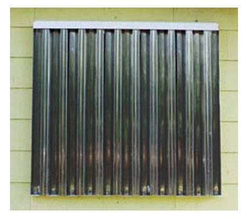
The highest level of protection normally available for windows is professionally produced shutters that meet the Dade County standards for opening protection. These standards require that the product be able to resist the impact of a 9 lb 2×4 traveling at 34 m.p.h. without penetration of the shutter, and if installed according to the manufacturer’s recommendations, not break the glass behind the shutter.
This level of protection can also be achieved for small to medium sized windows by making the shutter of out a 1/4 inch lexan sheet. This has the added benefit of providing a transparent shutter that will allow light in if the power goes out. The disadvantage is that the cost of lexan has continued to climb as oil prices have gone up. (A 4 x 8 sheet currently costs just under $200.) If you are making and installing your own shutters, you may want to consider this for your most critical windows, and the ones that allow in the most daylight.
It takes about a 3/4 inch thick piece of plywood to provide close to the same protection as the Dade County approved products, and that will make for a very heavy shutter. You can of course use thinner plywood (and IBHS recommends plywood over oriented strand board, or OSB, because it takes 30% thicker OSB to equal the impact resistance of plywood.) Recognize that the resistance to penetration by windborne debris is reduced in direct proportion to the thickness of the plywood. In other words, a 3/8 inch thick plywood shutter would be only about half as effective in resisting penetration as a 3/4 inch plywood shutter. IBHS recommends 5/8 inch thick plywood as a minimum unless you are having problems with handling the weight of the shutter.
Some layer of plywood will always be better than nothing, as long as it remains in place and even the thinner sheets will help resist the most common impacts from small ends of branches and shingles. If you live in a community with tile roofs, IBHS strongly recommends you seriously consider Dade County-approved shutter products for your windows. Our post-hurricane damage assessments noted considerable damage caused by wind-borne debris from roof tiles set with mortar. If you are going to make and install your own shutters, take the time to pre-install the anchorage hardware and prepare your shutter materials now, before a storm threatens. Pick out and purchase the material you want to use and cut it to the appropriate size for the type of installation you select. There are a lot of ways to install shutters that will work just fine and probably many more that won’t work well in a hurricane.
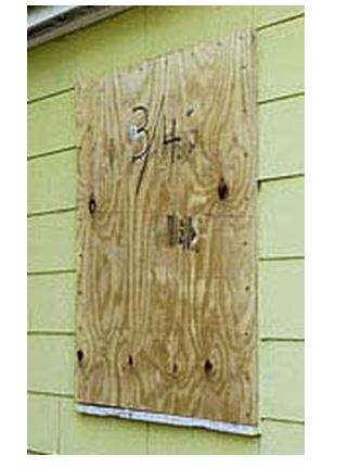
While you can nail plywood shutters as a last resort just before a storm strikes, repeatedly putting them up and taking them down will damage the area around your windows and doors, and ultimately affect anchorage quality.
For installations on wood frame walls, you can order stainless steel studs that have wood threads on one end and machine threads on the other end. Search under hanger bolts for the types of hardware you need. Select steel anchor bolts for permanent installations.
Stainless steel sleeve
RESOURCES
anchor for hollow or
Contractors Depot solid masonry.
Grainger
Jamestown Distributors
MSC
Wej-it
Protecting Doors
All doors should have three hinges and a dead-bolt lock with a minimum one-inch bolt throw length. Metal or solid wood doors may withstand hurricane pressures and wind-blown debris, but if you have French doors, doors with glass or hollow-core doors, you may want to shutter them.
Add barrel bolt restraints to the inactive door of double-doors to help keep them from bursting open during a storm. Make sure the bolts connect through the door header and through the threshold into the subfloor.
Additional Steps to Consider
Shutter and seal gable end vents to prevent wind-driven rain from entering attic space.
Use a high quality silicone caulk around outside wall openings such as clothes dryer, kitchen or bathroom vents, outdoor electrical outlets and locations where cables or pipes go through the wall. Just before a storm, close dryer and bathroom vents with duct tape (but remove it after a storm, before using the vents.)
Consider cutting wall screens in pool enclosures just before the storm hits, if you are still there and your property is located near the landfall position. This may save the aluminum enclosure.
In addition, politics:
The Growth Management Committee approved CS/HB 835, incorporating all but one of the Florida Building Commission’s recommendations involving wind resistance standards and windborne debris regions. The exception is that the amendment adopted by the committee no longer contains a section that repeals the one-mile carve-out in west Florida from the five-to-six-mile inland windborne debris regions established by the American Society of Civil Engineers.
Windborne debris regions from Franklin County westward through Escambia County would continue to be limited to one mile from the water, even though the regions would be five to six miles inland in most areas and up to 20 miles in some sections under pure implementation of ASCE 7-98, currently in the Florida Building Code.
The package does include language that will facilitate elimination of the internal pressure option to shutters and impact resistant glass in windborne debris regions; grant authority to the building commission to adopt by rule updated versions of the ASCE windborne debris region maps and wind resistance standards, except in the west Florida exemption area; and authorize the commission by rule to address exposure category C issues in the building code.
Do Kim, insurance community representative on the Building Commission, said today the amended bill contains some very important provisions even if it no longer repeals the Panhandle carve-out from ASCE 7.
A coalition, including various product manufacturers and FIC has been meeting with the Florida Homebuilders Association for weeks. The homebuilders adamantly refused to accept expansion of the windborne debris regions in the Panhandle and threatened to block passage of any package. Leaders of the coalition agreed to the amended legislation passed by the Growth Management Committee Tuesday night.
The FIC Property Committee continues to strongly support repeal of the Panhandle carve-out, but also supports what is left in the package. FIC lobbyist Charley Dudley, lead lobbyist on building code issues, hopes to keep the issue alive by legislative authority for a study of the impact of Hurricane Ivan, which would provide information for expansion of the debris regions in the future.
Other building code issues arising from the 2004 hurricane season will also be addressed by legislators as well.
This means, stay tuned, more is yet to come!
Conclusions
I encourage students who wish to do further research to do so. A wonderful place to start locating state codes is www.findlaw.com. From that website, which indexes online sources of state and federal law, one can “click through” to sources of constitutional, statutory, administrative, and case law for the federal government and all 50 states. Get involved. Check it out.