
Membrane Filtration – Process, Products & Materials
Upon completion of this course, you will understand:
- The basics of the four different membrane types, including reverse osmosis, nanofiltration, ultrafiltration and micorfiltration
- The materials used for membranes, including integral membranes and composite membranes
- The basics of chemical resistance, pH and temperature resistance of the various membrane materials
- The different element types, including spiral wound elements, tubular membranes, plate-and-frame systems and other more specialized types
- The limitations of membranes and systems
INTRODUCTION
Membranes are being put to hard work today, but they are relatively unknown to consumers since they are usually hidden within industrial processes. Some industries depend on membranes for the manufacturing of basic products, others need membranes to solve complex separation processes, while others again use membranes to meet environmental standards. The text for this course is taken from “Membrane Filtration Handbook, Practical Tips and Hints,” by Jørgen Wagner. The complete guide can be purchased from SPRI at the following website: Membrane Filtration Handbook, Practical Tips and Hints
MEMBRANE FILTRATION Process, Products and Materials


Four Membrane Processes
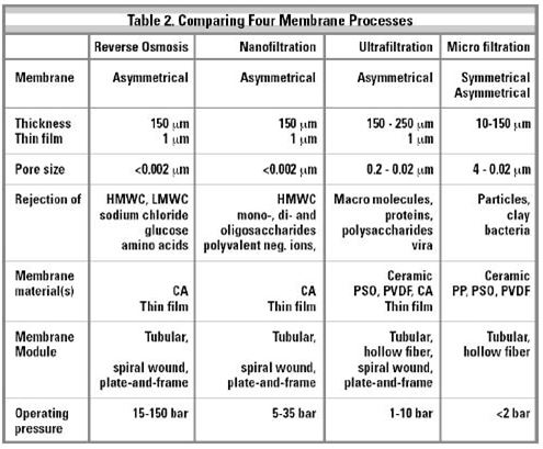
Reverse Osmosis (RO) is the tightest possible membrane process in liquid/liquid separation. Water is in principle the only material passing through the membrane; essentially all dissolved and suspended material is rejected. The more open types of RO membranes are sometimes confused with nanofiltration (NF).
True NF rejects only ions with more than one negative charge, such as sulfate or phosphate, while passing single charged ions. NF also rejects uncharged, dissolved materials and positively charged ions according to the size and shape of the molecule in question. Finally, the rejection of sodium chloride with NF varies from 0-50 percent depending on the feed concentration. In contrast, “loose RO” is an RO membrane with reduced salt rejection.
This effect has proven desirable for a number of applications where moderate salt removal is acceptable since operating pressures and power consumption are significantly lowered. So, in exchange for less than complete salt removal, costs are reduced.
Ultrafiltration (UF) is a process where the HMWC, such as protein, and suspended solids are rejected, while all LMWC pass through the membrane freely. There is consequently no rejection of mono-and di-saccharides, salts, amino acids, organics, inorganic acids or sodium hydroxide.
Microfiltration (MF) is a process where ideally only suspended solids are rejected, while even proteins pass the membrane freely. There is, however, quite a gap between real life and this ideal situation.
Products And Processes
A vast array of products are being treated using membranes, but water desalination is using over 80% of all membranes having ever been sold. The better portion of the remaining 20% are used for dairy processing, while the remaining are sold for use with many different liquids. Some liquids are waste products, while others are very expensive pharmaceutical products. Table 3 lists some typical applications, the shaded area representing the main product. Note that the permeate as well as the concentrate can be the desired product, and they can be that simultaneously.
Membranes, Materials, Structures, Limits
MEMBRANE MATERIALS

The selection of membranes offered by the various suppliers in the business may appear to be confusing since many materials may be used to make membranes, and they are provided under an array of trade names. In reality, relatively few materials are actually used in quantity, and only a few basic membrane types form the bulk of the membranes being sold and used.
INTEGRAL MEMBRANES
Cellulose acetate (CA) is the “original” membrane and is used for RO, NF and UF applications. The material has a number of limitations, mostly with respect to pH and temperature. The main advantage of CA is its low price, and the fact that it is hydrophilic, which makes it less prone to fouling. There are many “die hard” membrane users who insist on buying “the same membrane as last time,” and who simply stay with CA because it works for them. An inherent weakness of CA is that is can be eaten by microorganisms.
Polysulfone (PSO) in a number of varieties has been used for UF and MF membrane since 1975. PSOLs main advantage is its exceptional temperature and pH resistance. PSO is practically the only membrane material used in high quantity for a number of food and dairy applications. As a rule, PSO membranes do not tolerate oil, grease, fat and polar solvents. However, there is one type of hydrophilic PSO membrane which apparently defies this rule and seems to work well with oil emulsions.
Polyvinylidenedifluoride (PVDF) is a traditional membrane material, but it is not used much because it is difficult to make membranes with good and consistent separation characteristics. Its main advantage is its high resistance to hydrocarbons and oxidizing environments.
COMPOSITE MEMBRANES
Also called thin-film composite membranes, they appear under various acronyms such as TFC and TFM , and were made to replace cellulose acetate RO membranes. The main advantage is the combination of relatively high flux and very high salt rejection, 99.5% NaCl rejection commonly achieved with composite RO membranes. They also have good temperature and Ph resistance, but do not tolerate oxidizing environments.
Composite membranes are made in two-layer and three-layer designs, the precise composition of which is proprietary. Generally speaking, a thin-film composite membrane consists of a PSO membrane as support for the very thin skin layer which is polymerized in situ on the PSO UF membrane. The three layer design has two thin film membranes on top of the PSO support membrane.
Around 1980, FilmTec marketed the two-layer design which immediately became the industry standard for water desalination, and this type of membrane has dominated the water desalination market ever since. The membrane has been improved over the years but the basic design remains unchanged, and today there are several companies making this type of membrane.
In the mid 1980s Desalination Systems, Inc. (DSI) began making composite membranes with a three-layer design. These membranes had difficulties competing with the two-layer membranes in water desalination, but proved to work better on industrial process streams where it is more stable and less prone to fouling. The three-layer design is available for RO and NF, and it is still the best choice for treating a vast array of difficult process streams. DSI is the only producer of three-layer composite membranes.
Total worldwide consumption of membranes, based on membrane surface area, is approximately as follows.
Composite RO membranes: 85%
Composite NF membranes: 3 -5%
Polysulfone UF and MF membranes: 5 -7%
Other membranes: 3 -5%
Materials like polyacrylonitrile (PAN), ceramic materials (SiO2) and cellulose (hydrolyzed cellulose acetate) are included in the group of “other membranes.”
SELECTION OF MEMBRANE MATERIAL
It can be difficult to select the right membrane and membrane material for a given process, and some general information about the process environment must be available to make a proper selection. The first step is to determine the preferred process (RO, NF, UF or MF) and look at the membrane materials available. Based on the process environment the best suited membrane material can then be selected. Table 2 (Comparing Four Membrane Processes), Table 3 (Products and Processes) and Table 4 (Chemical Resistance of Several Membrane Materials) may be helpful in membrane selection.
Except for established applications, the choice of membrane material may be difficult, and more than one membrane material often comes into question. As a general rule, only well planned and well performed pilot tests will provide good answers to membrane selection questions for given processes.
pH AND TEMPERATURE RESISTANCE

In the section “Membrane Materials”, the pH resistance of the various materials was discussed. When deciding on a membrane process, it is not enough to look at the membrane material. Membranes come in several configuration (plate-and-frame, tubular, spiral wound, etc.) and a membrane system may include a number of other components which have restrictions with respect to pH tolerance. The pH limitations stated by most membrane manufacturers are in reality the limitations presented by the overall membrane configuration or membrane system rather than by the membrane material itself, the weakest material in the whole system determines the limitation.
The predominant membrane configuration is the spiral wound element, and although the following observations are valid for all membrane configurations, the spiral wound element has been chosen as the example.
Membranes are usually cast on a backing material which often is the limiting factor. The most widely used backing material is polyester (PE) which has excellent temperature stability, but limited tolerance to high pH environments. As a result, many membrane specifications state a maximum 11.5 pH limit. However, many membranes can be cast on polypropylene (PP) backings, which have excellent pH stability but limited temperature tolerance, which can make membrane production problematic. The point is that when a suitable membrane material has been identified and a membrane configuration has been chosen, it must be ascertained that this combination is available in a form which will withstand the working environment of the process.
Since spiral wound elements contain many different polymers, there may be other limiting factors than those set by the PE backing material. The central tube and the Anti-Telescoping Device/Interconnector (ATD/IC) are commonly made of PVC or ABS, but neither of these materials have great temperature resistance. PSO is a more expensive material which provides both good pH and temperature resistance, thus it is commonly chosen for central tubes and ATD/ICs in industrial processing.
A specified pH-limitation may be flexible to some degree and can be exceeded for short periods and under the right conditions without detrimental effects. Low pH is usually not as problematic as high pH. Exceeding pH limitations with elevated temperatures is almost guaranteed to cause problems.
COMPOSITE MEMBRANES AND OXIDIZING ENVIRONMENTS
The world is still waiting for a good composite membrane for RO and NF which can tolerate e.g. 20 ppm sodium hypochlorite. Some readily available composite RO membranes have chlorine resistance, but they do not stand up to todayDs general performance demands and any claim made for chlorine resistant should be taken with a grain of salt. In contrast, most TFMs tolerate hydrogen peroxide reasonably well, at least in limited concentration, at low temperature and for short durations of time.
MEMBRANE STRUCTURE
Literally all RO, NF and UF membranes are asymmetric. This differentiates most membranes from common filters, e.g. coffee filters, which are symmetric or, in other words, are identical on both sides of the filter. Membranes have a tight top layer facing the product to be treated. This layer is also called the skin layer. It is thin, typically <<0.1 micron. The membrane itself is 150 -250 micron, the bulk of the membrane simply providing structural support for the skin layer. The asymmetric structure means that the pores are wider and farther away from the surface, which prevents the pores from being plugged. This provides good fouling resistance, since foulants have a tendency to either be totally rejected or to pass all the way through a membrane.
The pore size of membranes can, in broad terms, be stated as follows.

So far, pores have not been observed in RO and NF membranes using a microscope, but in spite of this, water passes through the membrane and salt is rejected. The lack of pores in NF and RO membranes means that even membrane scientists do not really know how or why these membranes function 35 years after the production of the first membrane, or at least they do not know in any detail. Let it suffice to say that the first membrane was tested by someone with a practical sense who saw desalinated water come through it. If he had only looked at the membrane through a microscope, he might have rejected it since it did not have any pores and supposedly would not have worked.
In spite of our lack of knowledge, we are able to predict the performance of an RO membrane to some extent. With NF membranes, it is more difficult, and today, if more than three solutes are present in a solution, one can only make an educated guess as to the results of an NF process, even when an accurate and complete feed analysis is available.
Membrane Module / Element Design
As previously mentioned, there are several membrane configurations available on the market.
The spiral wound element type is the workhorse in the membrane world. The spiral wound element design was originally made exclusively for water desalination, but the very compact design and the low price made it attractive to other industries. After a lot of trial and failure, redesigned elements emerged which can be used for a variety of industrial applications in the dairy industry, the pulp and paper industry, for high purity water, and at high temperature and extreme pH, but the number of membrane companies who really can and will develop and supply spiral wound elements for extreme applications is in many cases limited to one.

Figure 1a
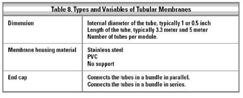
Tubular membranes have been around for a long time. The design is simple and easy to understand. Universities love tubular membranes because it is so simple to calculate the Reynolds number and to theorize about mass transfer coefficients. Tubular membranes have one big advantage. They can tolerate suspended solids, and most notoriously fibers, to a very high extent.
All tubular membranes suffer from several disadvantages:
- They require a lot of space.
- Change of membranes may be quite difficult and time consuming.
- The tubular systems with large ID (1 inch) use a lot of energy.
- Large internal volume makes flushing and CIP costly in terms of usage of chemicals and water.
- It is costly and difficult for the manufacturer to change the tubular design.
The advantages of the tubular systems sometimes outweigh the disadvantages, and the tubular membrane design has a place in the market, although quite small.
Plate-and-frame (flat sheet) systems were largely pioneered by DDS and actually dominated the dairy market in Europe for 15 years. Lack of development and an inflexible price structure more or less killed the design between 1989 and 1995.
There are several new plate-and-frame systems available in Europe. The best known is the ROCHEM design. Flat sheet systems offer a very robust and compact design, but for a price. Modern flat sheet systems are built to tolerate very high pressure, in excess of 100 bar. There is a small market for this extreme pressure range in treatment of landfill leachate and for desalination of sea water onboard ships.
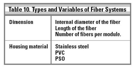
Fiber systems are (with one exception) similar to tubular systems. Only the ID of the fiber is small, typically <2 mm. The biggest difference from large diameter tubular membranes is that fiber systems are always unsupported. They came early on the market but are quite expensive. The fiber systems are mechanically weak. They have been used to a limited extent for UF of whole milk and are now used also for oil emulsions.
Ceramic systems are very, very expensive. Theoretically, ceramic systems can be very effective for MF. In reality the market is diminutive.
Hollow Fine Fibers was pioneer by DuPont for sea water desalination. They demand extremely good prefiltration. DuPont has ceased production.
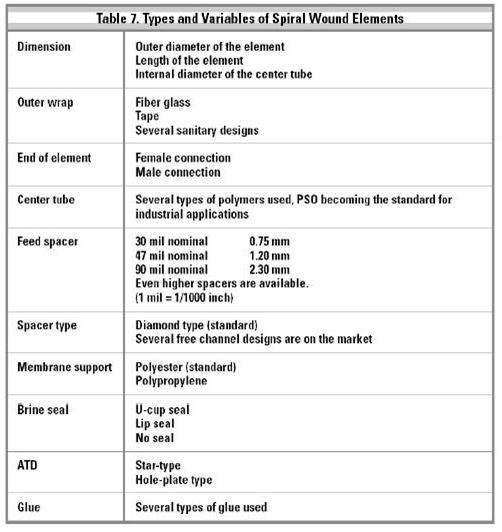
TYPES AND VARIABLES OF SPIRAL WOUND ELEMENTS
There is an incredible array of spiral wound elements on the market. In Table 7 some of the variables are listed.
TYPES AND VARIABLES OF TUBULAR MEMBRANES

TYPES AND VARIABLES OF PLATE-AND-FRAME SYSTEMS
The name “plate-and-frame” covers membrane modules of very different constructions, all using flat sheet membranes. The other systems mentioned will usually be easily recognizable as a spiral wound element, tubular membrane or fiber systems. Not so for the plate and frame modules. What they have in common is a flat sheet membrane, but the arrangement of plates and membranes in a module differs widely. The major plate and frame producers is shown in Table 9.

TYPES AND VARIABLES OF FIBER SYSTEMS
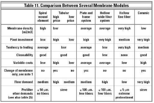
COMPARING MEMBRANE MODULES AND ELEMENTS
The following table is a qualitative comparison of the capabilities of various membrane module and element types.
More About Spiral Wound Elements
HOUSING DESIGN
There are several different designs of housings on the market. The housings can be segmented by material (stainless steel and polymer), or by function (housings with a side port entry and exit, or with entry and exit through the end caps).
Polymer housings are almost exclusively made from glass Fiber Reinforced Polyester (FRP). The design is over 30 years old and works well, but is certainly not without problems. It functions well in systems for desalination of ground water and sea water. For all other products its use is problematic. Most polymer housings use a tension ring to secure the end cap.
Stainless steel housings were originally made for dairy use exclusively. Today they are used much more widely, and are constructed with side ports as standard. Some stainless steel housings are constructed in the same way as glass fiber reinforced housings, which makes it exceedingly difficult to remove the caps. Stainless steel housings should be electro-polished on the inside. Otherwise it is next to impossible to push elements in and out of them.
There are only three standard diameters for glass fiber reinforced housings: 2.5-inch, 4-inch and 8-inch. Stainless steel housings are available in a wider variety of standard and non-standard diameters.

Unfortunately for Europeans, stainless steel housings based upon American inch measurements are most commonly used. The standard dairy sizes are not too difficult to obtain, but the 2.5-inch, 4-inch and 8-inch diameters are rare in Europe and quite difficult to find.
See Table 12 for a summary of the discussion above.
Stainless steel housings with side port entry and exit are available in two varieties: the 4-port style, which uses the housing as a building block with no external product manifold, and another type which uses an arrangement with external manifolds. (See Figure 1). One can argue which type is better, but it is a fact that most systems are built with external manifolds.
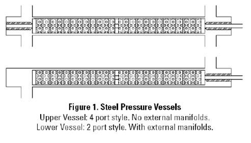
The main advantage of side entry is that it allows the high flow needed in sanitary systems. In water desalination this design is rarely used.
The world of spiral wound element dimensions is a jungle. Outer diameter, element length and internal diameter of the center tube is not standardized. This makes it quite difficult to change from one element manufacturer to another, and it creates a lot of problems for the housing manufacturers.
NUMBER OF ELEMENTS PER HOUSING -PRESSURE DROP
In order to determine the maximum number of elements per housing, several parameters must be considered:
First make a distinction between RO/NF and UF/MF
Then review the process
Third, take into consideration that an element can tolerate only a limited pressure drop Two main points shall be discussed in more detail.
Trans-membrane pressure (TMP)
Pressure drop per housing
Trans-membrane pressure represents the change in pressure between the inlet of a housing and the outlet of a housing. The pressure decrease is a result of feed passing through the elements. See Table 13 for an example.


It is easy to see that when the feed pressure is, for instance, 10 bar the difference between trans-membrane pressure at the inlet and the outlet is small enough to be considered unimportant. But when the feed pressure is in the range of 1 to 5 bar, there is a huge difference in trans-membrane pressure. Since it is best to have the same trans-membrane pressure for all elements in a housing, the maximum number of elements is smaller for low pressure operation.
Limitations Of Membranes And Systems
TEMPERATURE: MEMBRANES IN GENERAL
CA as a material has an inherent temperature limitation, and CA membranes are limited to an upper operating temperature of approximately 35°C.
PSO, PVDF and PAN can tolerate higher temperatures. PSO and PVDF membranes are known to operate at 95°C without problems. PSO membranes will operate at temperatures up to 120°C.
Composite membranes can, as a general rule, operate at least up to 80°C, and they will withstand higher temperatures at low pressure during, for instance, thermal disinfection.
The temperature capability of a membrane system is, in most cases, not dictated by the temperature limitation of the membrane, but primarily by the membrane configurations and other components in the membrane system.
SPIRAL WOUND ELEMENTS
Spiral wound elements traditionally have had an upper temperature limit of 45°C. This is still valid for standard elements used for water desalination, but there are now spiral wound elements available on the market capable of higher temperature limits. Although a maximum temperature of 45°C is not a limitation in water desalination, it is a problematic limitation for food and process industry applications. After much trial and error, a few companies have succeeded in producing temperature stable elements.
The elements used in the dairy industry have been operating at higher temperature (and pressure drop) than originally specified by the element producers for years. Today, the 55°C limit printed for a dairy standard element reflects the real limit; this temperature is rarely exceeded in normal dairy operations.
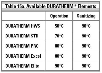
Osmonics has developed elements which have proven to tolerate temperatures well over 55°C. The elements are produced with a variety of spacers. They are sold under the trade name DURATHERM® membrane elements. The following elements are available mid 2001. (see Table 15a)

The product flux should be watched and kept below 35 lmh, thus ensuring that the operating pressure is kept low. It is also recommended to calculate the Wagner units.
Elements with wider feed spacers can operate on feed containing high dissolved solids. It is standard to use a 50 mil spacer, but wider spacers are available, e.g. 90 mil spacers, which allow treatment of even more difficult liquids. Depending on the type of membrane these elements can operate up to 90°C continuously. One example is elements from DESAL” membrane products under the trade name DURATHERM® Excel. The good temperature stability ensures that these elements can be thoroughly pasteurized, or that they can operate continuously at a temperature which is sufficient to make any discussion about microbial growth very academic.
UF of carrageenan is one of the processes where membranes have been operated at 80 -90°C for years. A more recent application is RO of evaporator condensate for silica removal, operating at close to 90°C.
Just for the record: DESAL” membrane elements have been pioneered for industrial sizes operating on non-water liquids at 140°C. This is probably very close to the limit for polymeric membranes.

Please see element specifications from the supplier for limitations which must be taken into consideration such as pH, flux and pressure.
A positive aspect of high temperature operation is the increase in flux that results from high temperature (See Optimizing Pressure and Temperature). Operation at 90°C will increase flux from 100% to 300% at the same pressure. But it is often better to reduce pressure (actually NDP) to one third and save substantial amounts of electricity.
High temperature can be viewed as problematic, but the author most often finds high temperature membrane operation to be advantageous even though the system must be engineered with more care and more emphasis on a number of details than normal. The main rule to remember is this: the higher the temperature, the more one needs to be aware of the physical stress on the elements and the membrane.
- Excessive trans-membrane pressure can flatten the membrane excessively (“compaction”), resulting in an irreversible drop of flux.
- Excessive pressure drop can cause membrane and/or polymer materials of construction to move and sometimes break, eventually resulting in a complete failure of the membrane.
SYSTEMS OTHER THAN SPIRAL WOUND ELEMENTS
- Fiber systems can usually tolerate temperatures up to 80°C.
- Low priced tubular systems with an unsupported membrane tube will normally be specified with a maximum operating temperature of 35°C.
- Higher priced tubular systems with a supported membrane, for instance a stainless steel support arrangement, can tolerate >80°C.
- Hollow fine fiber systems are limited to <50°C.
Plate-and-frame systems will, depending on the actual design, be able to operate at temperatures of >80°C. Older systems may have problems with pressure stability during high temperature operation.
PRESSURE
All membranes are sensitive to pressure. The word compaction is often used to describe the irreversible DflatteningD of a membrane due to pressure. Besides the membranesD own ruggedness, it is vital to properly support the membrane to prevent pressure squeezing the membrane into the support material.
It is important to read the manufacturer’s specifications and follow them carefully. This type of specification is usually based on experience rather than theoretical calculations, so why repeat somebody else’s bad experience?


Compaction is a function of pressure and temperature. (See Table 18)

There are no firm rules available regarding maximum allowable temperature and pressure. The guidelines in Table 18 are valid for all membranes, except CA membranes. Table 18a. provides some general rules concerning the temperature/pressure relationship expressed in what has been dubbed as Wagner units. Please note that temperature is more dangerous than pressure.
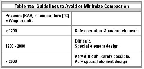
Consequently, when operating close to the upper temperature limit it is advisable to restrict pressure as much as possible.
pH

Most membranes, with CA membranes being the notable exception, are very resistant to extreme pH values. The major limitation is the use of polyester backing for many membranes, which limits the upper practical limit effectively to pH 11.5. The functionality of many membranes changes at very high pH values, but they may still be useful and functional. Most membranes are stable at low pH values.
FEED FLOW
There is no such thing as an absolute upper feed flow limit. The mechanical strength of the membrane module or element sets the limit.
VISCOSITY
Viscosity of the feed is not in itself a problem, but high viscosity leads to higher pressure drop for a given flow. As long as the pressure drop is acceptable and the flux is satisfactory and stable, viscosity does not pose an operational problem. Handling high viscosity feeds in a membrane system is more of an engineering problem than a membrane problem.
CONCLUSION
The four membrane processes are reverse osmosis, nanofiltration, ultrafiltration and microfiltration. Membranes are most commonly used for water treatment, but other industrial applications are also important. Reverse osmosis is the most common membrane process. The various membrane materials have different limits of temperature and pH. The spiral wound element is the workhorse in the membrane world. Other membrane types include tubular membranes, plate-and-frame systems, fiber systems and ceramic systems.
One has to remember also that in salt water systems larva from marine organisms such as mollusks can pass initial filters, then attach themselves to the filters and effectively blind filters such as what happened in Tampa, Florida.