
Basic Civil Engineering – Sewers and Sewerage
Course Description
Piping, underground structures and pumps are just a few of the items needed when moving wastewater to an area where it can be treated. When designing sewerage, there are different methods to look at, and there are pitfalls you must be careful to avoid.
In this course, we will look at types of pipe, manholes, lift stations, force mains, and regulations.
Learning Objectives
At the conclusion of this course, you will be able to:
- Recall the terminology and history associated with sewerage projects
- Perform the necessary tasks to ensure the sewerage job is completed successfully
- Identify the types of sewer lines
- State current regulations for sanitary sewer overflows
Introduction
During a visit to Crete, we toured an excavation of a large building that they were uncovering. We were told that it was built in 3000 BC. One item of interest was what was described to us as the “bathroom.” It was in the center of the building on the second floor, and consisted of an area about 4 feet square. It appeared that originally, there were walls on two sides and just a 3 inch high sill on the other two sides. There was a gouged out trough behind the sill leading up to a hole in the floor about 2 inches in diameter. The trough started about 1/4 inch deep and was 2 inches deep when it got to the hole. It appeared that water was introduced from above and was collected and conveyed away below. At that point, they had not excavated under this part of the second floor yet, but I would love to go back and see if they found out where the discharge led!
The piping or other means they used to convey the water away from the building is similar to systems we use today. While these days the floors are seldom made of stone, and pipes are plastic for the most part, the concept is the same: water flows downhill and we use that to convey it away.
For many years, water leaving the house was conveyed to the nearest creek or lake. In Europe and many other countries, it was conveyed into gutters in the street. In the U.S., many of the older systems are combined sewers, meaning the stormwater conveyance system was also the system used for the home wastewater.
Present
Today, for the most part, the wastewater is conveyed to a location where it is treated. The conveyance pipe is called a “sewer” line, and the system of sewer lines that make up a collection system is called “sewerage.” Sewerage can be as simple as the collection of pipes from a small village up on a hillside above a lagoon into which the wastewater is run via gravity, to a complex system of gravity lines, pumps, floats, manual valves, surge tanks, electrically operated valves, and the like, all radio controlled from the main treatment plant. In each case, the system needs to convey the waste consistently, and for as long a time as possible without fail.
What are we conveying? In the typical residential system, we need to convey the chopped up vegetables from the garbage disposal, human waste, and, as anyone who has spent time at the grate at the treatment plant, any number of things that come down the line. This includes the priceless figurines my father had brought back from Japan during the Second World War. My 4 year old sister thought it was neat to carry them, one at a time; smash them into the toilet bowl, flush, and then go for the next one from the china cabinet. Our sanitary lines need to carry it all.
Collection Systems
One of the first things you must decide is whether the collection system should be a gravity system (which consists of individual gravity lines that lead to a gravity trunk main to a lift station), or a pressure system (which is a gravity line to a pump at each source, then a series of force mains to the treatment location).
The City of Port Richey, Florida had a problem: most of the city had developed without a central collection system. The city wanted to create a sanitary system to include the population, but there were several impediments. One impediment was the limerock was very close to the surface, usually with about 5 feet of sand cover. Cutting deep into limerock to lay gravity sewers was going to be quite costly. Some of the limerock was very, very hard; it could only be excavated efficiently by blasting it. This is not easily done within a subdivision!
The solution designed for the city was a pressure system. Each home had a small pump station (similar to an overgrown garbage disposal) situated at the lot line. Each pump station could pump against a 100 pounds per square inch head and was connected to a main pressure line, which was to be constructed along the right of way. The pressure in the main pressure line was designed to be 60 psi with 1/4 of the attached pumps pumping at any given moment. The maintenance of the thousands of pumps was to reside with the city. The pump stations were small enough to be removed with a backhoe, and the defective lift station removed to the yard for servicing.
One downside to this design was the possibility of power outages.
Piping
Over the years, pipe lines have been made of any number of materials; stone, wood, clay, steel, cast iron, asbestos cement, wrought iron, brass, brick, riveted steel, glazed brickwork, plastic, and even rubber. The coefficient of friction of all of these varies in their original condition, but they all become much the same after a few years of use. The grease, oils and small particles in the wastewater will fill in the pores and irregularities of pipes and coat the smoothest of pipes, ending up with a uniform coating on almost any pipe.
In many cities, the line from the home to the main gravity line is to be 6 inches in diameter, but 4 inch is still used for smaller homes (you may find 3 inch and even 2 inch lines in some older systems). The slope of sewer lines is designed to carry solids as best as the pipe can without getting so steep that the excavation gets too expensive. The higher the slope, the faster the water will flow; the faster the water flows, the more the solids will be kept in motion, and the less the lines will plug. The slope of 1% for 4 inch pipes, 0.67% for 6 inch lines and 0.4% for 8 inch lines will provide approximately 1.5 ft per second flow (or partial flow), and will usually function satisfactorily. In practice, even a small negative slope can be tolerated. The size of the lines is usually sufficient to overcome the problem. “Bellies” in plastic pipe have been functioning for decades. This is when the middle of the length of pipe is lower than the ends. That is not to advocate them, but this is not “rocket science.” Digging up a line because of minor defects is not usually effective.
In some cases, inverted siphons are created to allow the pipeline to go under obstructions. Such structures must be designed with extreme caution as they have the nasty habit of filling up with sand or other material, and plugging up at the most inopportune times. A manhole at each end of the lower line is one way to help, but the man in the lower manhole attempting to unplug the line needs to be careful. The upper manhole needs to be pumped dry prior to his work, or he may be carried away when the plug lets go!
One major problem with today’s plastic sewer lines is just that, they are “plastic,” or subject to deformation. Control of the bedding and backfill for plastic piping needs to be examined very closely. A sizeable rock laid over the pipe may not cause a problem with other types of pipe – and may not be evident upon the lamping or videotaping of a plastic line shortly after construction – but may crush the plastic completely over the next decade! (On another note, all sewer line excavations must be made with an eye toward safety. I once watched as a large 4 foot diameter stone slid out of the side of an excavation and crushed a man.)
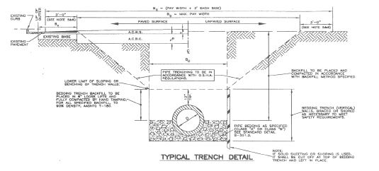
Here is an example of a typical excavation and bedding detail.
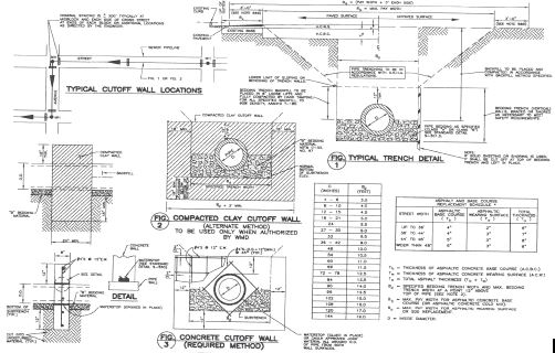
Here is one detail from a typical excavation and bedding.
In addition to the bedding, crossings of other pipes are very critical. Here is a detail of that condition.
I once inherited the piping design of a mall. The engineers in another state had designed the gravity lines to conduct the wastewater from the entire mall to one lift station. The sewer lines were started at the north side of the mall. One line went west, then south, then east to the center of the south side of the mall. The other line went east, then south, then west to the same lift station.
The gravity lines needed to accommodate that system needed to be 40 feet deep. In Florida, a 40 foot deep line will quickly eat up a million dollars due to limerock and water control problems. The limerock was hard but porous. You could not drive sheet piling to keep out the water, so you had to excavate hard limerock underwater to a depth of 40 feet and then implement some water control to allow work to continue! I redesigned the system to have two lift stations with the deepest line being 20 feet, which was acceptable. Sometimes you must be creative to save your client millions!
Proper Design
Manholes
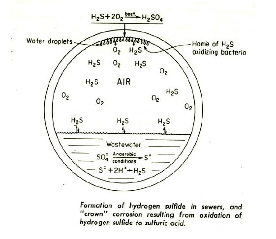
One word of caution, do not design manholes with built-in ladders! And, if you find a ladder built into a manhole, do not climb it. If a ladder is covered for years in a manhole, the hydrogen sulfide in the waste will combine with oxygen, and in the presence of bacteria, will create sulfuric acid. This will eat away any steel and make the ladders very unsafe. This detail shows the process in the pipe. The same process occurs on the manhole steps!
Manholes need to be constructed at every bend in the sewer line, and at the limits of the cleaning equipment. Local regulations may stipulate certain minimum lengths, but the cleaning mechanism to be employed (vacuum trucks, for example.) need to also be taken into account. It makes no sense to construct a line that cannot be cleaned ten years later!
Lift Stations
Lift station design is based upon the area serviced. An example would be a 200 lot subdivision. The flow from the subdivision is estimated to be 200 times 250 gallons, per day per lot, or 50,000 gallons per day. The lift station needs to be designed to hold five minutes of average flow, or 50,000 multiplied by the quotient of 5/1440 or 174 gallons. If the lift station is 6 feet in diameter, the capacity of one foot is 212 gallons, so the interval between pump on and pump off would be 174 divided by 212 which is .81 feet, or simply 10 inches.
The pump capacity is two times the storage, or 350 gallons per minute. There always should be two pumps which alternate. The pumps used should be designed to pass 4 inch diameter solids and be reversible to clear clogs.
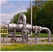
Force Mains
Force mains need to be designed to accommodate the flow without undue pressure, which increases cost, and with adequate velocity to keep the force main clean. The usual force main or pump design would include determining the static head from the “pump off” level to the discharge elevation. One would then add to this the friction head using a nomograph or Hazen-Williams formula. This total head would be used to design the pump or force main combination.
One unique system I ran into was that of a force main that ran from Honeymoon Island to the mainland of Florida. The force main was three miles long and ran up and over two bridges. I designed it the usual way, but after it was built and we were testing it, it performed strangely. The static head was showing correctly on the gage. Then the pump was turned on. The pressure increased for a while, then decreased so far it went negative! The wetwell was sucked dry! When we refilled the wetwell and started the pump again, it did the same thing again! What was happening was that as the water was pumped over the bridges, a siphon was created, saving us the trouble to pump the water! No harm was done, the pumps needed the head to get it started, but we got a free ride the rest of the way!
Regulations for Operations
Currently, there are requirements for sanitary sewer overflows or what is commonly known as SSOs. Discharges to waters of the United States from municipal sanitary sewer systems are prohibited, unless authorized by a National Pollutant Discharge Elimination System (NPDES) permit. Permits authorizing discharges from such systems must contain technology-based effluent limitations, based upon secondary treatment and appropriate water quality-based effluent limitations. Currently, NPDES permits for municipal treatment plants require recordkeeping and reporting of overflows that result in a discharge. However, the Environmental Protection Agency (EPA) realizes that even municipal collection systems operated in an exemplary fashion may experience unauthorized discharges under exceptional circumstances. Therefore, NPDES permits may provide a framework for evaluating specific circumstances of overflows which result in a discharge. In narrowly-prescribed circumstances, an overflow may be excused, either through the exercise of enforcement discretion or through establishment of an affirmative defense.
The EPA and the States continue to address SSO problems with compliance assistance and enforcement actions, in accordance with the Compliance and Enforcement Strategy Addressing Combined Sewer Overflows and Sanitary Sewer Overflows (issued on April 27th, 2000). This Strategy calls for each EPA Region to develop an enforcement response plan that includes an inventory of SSO violations. This enforcement response plan will also describe how 20% of the priority systems with SSO violations will be addressed each year. EPA is proposing revisions to the NPDES permit regulations to improve the operation of municipal sanitary sewer collection systems, reduce the frequency and occurrence of sewer overflows, and provide more effective public notification when overflows do occur. This proposal will provide communities with a framework for reducing health and environmental risks associated with overflowing sewers. The result will be fewer overflows, better information for local communities, and extended lifetime for the nation’s infrastructure. This rule primarily addresses sanitary sewer overflows, not combined sewer overflows, although the EPA does request comment on applying the proposed reporting, recordkeeping, and public notification standard permit condition to combined sewers.
Requirements include:
- Capacity Assurance, Management, Operation, and Maintenance Programs. These programs will help communities ensure they have adequate wastewater collection and treatment capacity, and incorporate many standard operation and maintenance activities for good system performance. When implemented, these programs will provide for efficient operation of sanitary sewer collection systems.
- Notifying the Public and Health Authorities. Municipalities and other local interests will establish a locally tailored program that notifies the public of overflows according to the risk associated with specific overflow events. The EPA is also proposing that annual summaries of sewer overflows be made available to the public. The proposal also clarifies existing record-keeping requirements and requirements to report to the state.
- Prohibition of Overflows. The existing Clean Water Act prohibition of sanitary sewer overflows that discharge to surface waters is clarified to provide communities with limited protection from enforcement in cases where overflows are caused by factors beyond their reasonable control or severe natural conditions, provided there are no feasible alternatives.
- Expanding Permit Coverage to Satellite Systems. Satellite municipal collection systems are those collection systems where the owner or operator is different than the owner or operator of the treatment facility. Some 4,800 satellite collection systems will be required to obtain NPDES permit coverage to include the requirements under this proposal.
National Enforcement Initiatives
EPA protects people’s health and safeguards communities by assuring compliance with the nation’s environmental laws and by taking enforcement action when laws are violated. Every three years, EPA sets national enforcement initiatives to focus civil and criminal enforcement resources and expertise on serious pollution problems affecting communities. The 2011-2013 initiatives were chosen with state and public input and support EPA’s seven priorities.
Air

Reducing Air Pollution from the Largest Sources
Cutting Hazardous Air Pollutants
Energy Extraction
Assuring Energy Extraction Activities Comply with Environmental Laws
Water
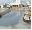
Keeping Raw Sewage and Contaminated Stormwater Out of Our Nation’s Waters
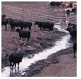
Preventing Animal Waste from Contaminating Surface and Ground Water
Hazardous Chemicals
Reducing Pollution from Mineral Processing Operations
Summary
A sanitary sewer system is used to collect wastewater. The content of that wastewater must be determined, and the solids in the stream must be carried to the end. Gravity systems and pressure systems are used to move the wastewater. In general, gravity lines and pressure lines must be designed to efficiently move wastewater and the solids therein.
Gravity lines must not be extended to such lengths that they exceed economical depths. An analysis of two or more systems should be made to insure that the cost is optimum.
Lift stations need to have multiplicity. Pumps fail, but your system should not. Consideration should be made for generator backup for the more important stations, and flood elevations should always be investigated and taken into account.
The systems must be made to work for decades without fail, and any discharge needs to be reported to the federal government!
Biography
John Herrick
Mr. Herrick is a Professional Engineer, a Professional Land Surveyor and Mapper, and a Microsoft Certified Professional. He is recognized nationally as an expert in claims analysis and resolution, CPM scheduling, project management, surveying and cost engineering.
Mr. Herrick is an active member of numerous professional organizations and has lectured extensively on topics such as productivity, CPM scheduling, surveying law, computer hardware and software and construction claims. He presents seminars which are attended by licensed professionals from across the nation.
Final Exam
1. What is the definition of sewerage?
- Wastewater.
- A pipe used to convey the wastewater.
- A system of piping, pumps, and other items used in the conveyance of wastewater.
- None of the above.
2. What is the definition of a sewer line?
- Wastewater from homes.
- A pipe used to convey the wastewater from homes.
- A system of pipes used to convey wastewater from homes.
- None of the above.
3. What is a characteristic of a pressure system?
- It uses gravity to convey the wastewater.
- It will work during power outages.
- It has few pumps.
- None of the above.
4. When bedding a pipe, which is true?
- Isolated rocks can damage plastic pipe.
- The bedding needs to be compacted and true to line.
- Bedding for plastic pipe is more important than for many other types of pipe.
- All of the above.
5. The flow of wastewater in a gravity pipe should be at the least:
- 0.5 feet per second
- 1.5 feet per second
- 10 feet per second
- 15 feet per second
6. What are the characteristics of inverted siphons?
- They cost much more than other methods.
- They are much harder to maintain than other methods.
- They are very safe.
- None of the above.
7. At all costs, one lift station is the best design.
- True, the maintenance of multiple lift stations is too costly.
- True, the space taken up by multiple stations is wasteful.
- False, the cost of construction and of pumping may be less with multiple stations.
- None of the above.
8. Which of the following statements is true?
- You should construct manholes to accommodate the cleaning equipment.
- You should construct manholes at every bend.
- You should construct manholes at the lengths required by law.
- All the above.
9. The capacity of the storage in the lift station should be:
- Five minutes at average flow.
- Ten minutes at average flow
- Fifteen minutes at average flow
- Five minutes at peak flow.
10 The pump/force main combination should be designed to drain the storage down in what ratio?
- Pump capacity to be same as storage capacity.
- Pump capacity to be two times storage capacity.
- Pump capacity to be three times storage capacity.
- Pump capacity to be four times storage capacity.
Spreadsheet FTP://www.herrickhomepage.com/wp/public_ftp/SanitarySewerx.xls