

Course Name: Basic Civil Engineering – Culvert Design (1 hour)
STORMWATER
Gravity Flow Gravity flow through pipes not under pressure is usually determined using the Manning formula developed by Robert Manning. Robert Manning was an engineer born in Wicklow, Ireland. He had a long career in Dublin and Belfast during the latter half of the 1800’s. He is famous for hydraulic engineering and in textbooks for the “Manning Coefficient”, still in use to describe water flow in open channels.
The most commonly used empirical equation to determine open channel flow is Manning’s Equation:
v=K/n R2/3S1/2(English Units) [SI units]
v = Fluid Velocity (ft/s) or [m/s]
K = 1.486 (English); K = 1.00 [SI]
R = Hydraulic Radius (ft) or [m] = A/Pw
A = Cross-Sectional Area of Flow (ft2) or [m2]
Pw = Wetted Perimeter (ft) or [m]
S = Channel Slope
n = Manning’s Roughness Coefficient
The cross-sectional area to flow and wetted perimeter are related to the depth.
Pressure Flow Flow through pipes under pressure is usually determined using the Hazen-Williams formula (An equation developed in 1902 by Gardner Williams and Allen Hazen to express flow relations in pressure conduits):

In this equation the roughness coefficient is C. The other factors are the same as the Manning Formula. NOTE: The Hazen Williams formula is for a maximum internal velocity of 22 fps. If you ABSOLUTELY have to exceed 22 fps use a friction loss calculation program based on the laminar/turbulent flow equations of Darcy-Weisbach, a standard civil engineering calculation method. You would no longer be designing a system that will work in the long run due to scour, but at least the flows and pressure you calculate will be closer to what actually occurs in real life. Typical roughness values:
Values of C in Hazen-Williams formula, taken from Williams and Hazen’s book. “Hydraulic Tables” and other authorities. C =145 : Asbestos-cement pipe.
C =140 : Bitumen-lined steel pipes; smooth concrete pipe; smooth pipes of brass, glass or lead.
C =130 : New coated cast iron pipe; small brass or copper pipe.
C =125 : New uncoated cast iron pipe.
C =120 : Smooth woodstave pipe.
C =110 : Riveted steel pipe; vitrified pipe,
C =100 : Brick sewers.
For old or encrusted pipes the value of C may be as low as 80 or less, depending on the actual condition. VALUES OF MANNING’S “n” FOR CHANNELS
n = .009 : straight channels of smooth planed boards.
n = .010 : neat cement plaster.
n = .012 : unplaned boards; sand and cement plaster.
n = .013 : steel trowelled concrete; metal flumes.
n = .014 : wooden troweled concrete.
n = .015 : ordinary brickwork or smooth masonry.
n = .020 : channels in fine gravel; rough set rubble; or earth in good condition.
n = .025 : canals and rivers in fair condition
n = .030 : canals and rivers in poor condition.
n = .035 : canals and rivers in bad condition, say with bed strewn with stones and detritus.
n = .040 : canals half full of vegetation.
n = .050 : canals two-thirds full of vegetation.
As the Manning formula is sometimes used for flow in pipes, the following table of values of “n” may be useful. The value of V being found by the Manning formula on the “channels” side of the rule, this may be applied on the “pipes” side to find the flow. VALUES OF MANNING’S “n” FOR PIPES
n = .010: Asbestos-cement pipe
n = .011: Concrete pipe; very smooth.
n = .012: Clean coated cast iron pipe; woodstave pipe.
n = .013: Clean uncoated cast iron pipe.
n = .014: Vitrified sewer pipe; riveted steel pipe.
n = .015: Galvanized iron pipe.
n = .016: Concrete pipe with rough joints.
n = .021: Corrugated metal pipes.
Old or badly encrusted pipes will require higher values of “n” depending on the actual condition. In addition, the following table may be useful (thousands of values of “n” have been computed, the internet is a great place to find the one you may be looking for): MaterialManning (n)Hazen-Williams (C)
Plastic, copper 0.009 160
Concrete – Smooth 0.011 120
Concrete – Design 0.013 100
Corroded Cast Iron 0.020 60
Typical design criteria:
When designing pipes, one of the most important aspects is the velocity of the water. Too low, and sedimentation builds up in the pipe causing the flow to become blocked and then requires the pipe to be cleaned regularly. Too high, and the flow of the water causes the pipe surface to be scoured and can result in pipe failure and expensive renewal work. A typical value of the velocity is 3 feet per second [1 m/s]. Minimum cover for pipes is usually 2 feet [0.6 metres] to prevent damage by vehicles (cars, not trucks) that may drive across them.
Now, lets get down to practical matters.
Manning’s formula is great but how does one apply it? In today’s world of the internet, there are web sites one can go to, enter the data you know, and out pops the remaining data relative to your design. This is wonderful, but there are too many parts to the puzzle at first for one to start there, so save that for a check on your design after you have worked out most of the wrinkles.
To start with, one needs to know how much water is going to come to any given culvert. One can use any number of empherical methods, but let’s start with a basic one. Q=Aci (the Rational Formula). Assuming that one has determined the area draining to the culvert (A) and the intensity of the storm is known (i), all one needs is the coefficent of runoff (c).
For the most part, subdivisions have a coefficient of .5, so if the rainstorm you have in mind is 4 inches per hour at a typical concentration time, all one has to do is multiply the acreage coming to each inlet by 2 to determine the cfs (cubic feet per second) one has to contend with. Assuming that your initial culvert collects from 1 acre, you need to design for 2 cfs.
Use the local “RAINFALL INTENSITY DURATION” curves to determine your actual intensities and “Overland Flow Charts” for inlet concentration times, see example below – on the left is the length of run, next is the type of surface [paved up to dense grass], the pivot line, the slope, then the inlet concentration can be found on the right. This is just an example; when you need to perform this calculation, a real paper one needs to be obtained so you can draw the lines to determine the time.

DESIGN
Now the trick is to design the most efficient system. The beginning point would be to select the highest point and the lowest point of your hydraulic gradient. The highest point should be about 18 inches below the elevation of the crown of the road at the high end, and the low being at 18 inches below the crown of the road ot the low end (and must be at or above the hydraulic grade of the receiving water). A straight line between them is the best place to start. This line will be where the 3/4 full line of your culverts should be. A simple sketch showing the rough topography between the two extremes of your project will show the big picture. If the terrain is rugged, you may not want to use a straight line – your pipes would be too deep (i.e., costly). If the terrain is very flat, you may want to use some swales or interim ponds to reduce the piping costs. In any event, an optimum slope will need to be determined from this sketch. For our example we will use a slope of 0.5 feet per 100 feet.
Now that we have the initial flow and the initial slope, the initial kind of pipe needs to be determined. Are you going to use corrugated steel, concrete, plastic, or whatever? Cost is a major factor, as well as maintenance. Lets assume that you decide on concrete for it’s long life. Let us summarize:
concrete pipe (n of 0.013 for good condition)
slope of 0.5%
Q of 2 cfs All we need now is to size the pipe.
Following is a graph I have created using a concrete pipe. Most manufactures have such graphs, just ask!

From this graph (or the one you got from the manufacturer), you can see that an 18 inch concrete pipe at 0.3% slope will carry 4 cfs at 3 feet per second. In our example, we only need to carry 2 cfs at 0.5% slope. That would have been fine in a 12 inch pipe, but, unless the pipe was really short, it would be impossible to provide adequate maintenance over the life of the system. An 18 inch pipe is the smallest culvert recommended.
As we move down the system, and flows increases (say 20 cfs) we find that we need a larger pipe, but the slope to maintain 3 feet per second is still very flat. Make sure 3/4 of your pipe remains at the hydraulic grade you have created, or your system will not work as efficiently as possible! As we do not want to get too high a velocity, the larger culvert might be better. It is always better (if you can) to have the culvert a little larger than smaller. The intensity of the storm will vary from not raining to a deluge sometimes. The difference might be in a flooded home or not! Once you have your system roughed out, you need to go back and refine it. An 18 inch culvert should have an invert elevation of 3 feet below the crown of the road, so if you need to, raise the road in places. This gives adequate cover so that the subbase, base and asphalt can be constructed. So, if you begin at the top and work your way downstream, adding flows as they come online, you can design your system.
Grates
The next step is to ensure that the grates and inlets are sufficient to allow the water to get to your culverts. The grate dimensions are the perimeter p=2(a+b) and the clear opening area A=aw*n, where n is the number of openings.
The next step is to insure that the grates and inlets are sufficient to allow the water to get to your culverts. I have scanned (below) what the graphs look like, but the detail is such that they do not scan well and it is best to get new ones (or use the formula!).
The grate dimensions are: p=2(a+b) and A=aw*n (n =the number of openings).
3/2
For head up to 0.4 feet, Q/p = 3H
1/2
For head above 1.4 feet Q/A = 5.37 H
This is what the nomograph would look like. The inlet dimensions are the length of the inlet opening (L), the height of the opening (h), and the height of the water in the opening (H).

For heads up to five times the height of the opening the flow is determined from this nomograph. For heads above five times the height of the opening, the discharge is calculated as an orifice which is beyond the scope of this course. Normally one would size the length of the opening to match the expected flow. This is done as follows:
Your flow to the inlet might be 2 cubic feet per second. This will be represented by Q. Assume that the height of your inlet opening is 3 inches. This will be represented by h. Assume that you will allow the water to be 1.25 times the height of the opening (H/h = 1.25). Place a straight edge on the nomograph at h= 3 (on the left) and rotate to 1.25 on the right side. Read Q/L of 0.5 cfs per foot in the center. Calculate the length of the inlet opening (L) from the factor Q/L of 0.5 cfs using this formula.
L= Q/ Q/L
Or in this case 2cfs/0.5cfs per foot, this calculates to 4 linear feet in this example.
Weir
The final item for discussion is the weir. Many times the discharge from your system needs to be controlled. The rectangular weir is one feature used for that purpose. Following is a table of values for various weirs, but they all can be computed as follows:

H is the height of water over the weir. P is height of the weir over the channel upstream and L is the length of the weir. (g is 32.17)
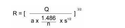
If a swale carries your water, Manning’s formula is used. The wetted perimeter is the length along the sides and bottom. The area is the area of the water at that point. The R is the area divided by wetted perimeter. Variations on the Manning’s Equation are:


| Summary Culverts are used to convey flow through an embankment or past some other type of flow obstruction. To calculate gravity flow through pipes that are not under pressure, you would use the Manning formula. Flow through pipes under pressure is usually determined using the Hazen-Williams formula. When designing pipes, one of the most important aspects is the velocity of the water. You can use the Rational Formula to determine how much water is going to come to any given culvert. You then must determine your slope by the gradient of the terrain as well as the type and size of the pipe. Finally, you will have to ensure that the grates and inlets are sufficient to allow the water to get to your culverts. You can then control the discharge from the drainage system with the use of weirs. |